5 itc mode – Rainbow Electronics ATMOS™ 1M60 User Manual
Page 9
9
5429B–IMAGE–04/05
[Preliminary] ATMOS -1M60/1M30
Therefore the minimum period is reduced to 1 × readout time. As the integration time is not the
same for all lines (in the following timing diagram line n integration time is greater than line 1
integration time) this mode must be used with a pulsed light source or a shutter element. More-
over any residual light when shutter output signal is inhibited must be avoided. The exposure
time is defined by the shutter time and all the lines are exposed during the same time.
See register Aperture Shutter Time @ 246H Internal Register Mapping on
page 15
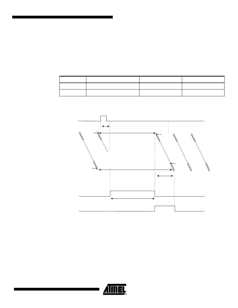
Figure 4-4.
Triggered Mode Without Full Reset Chronogram
4.1.5
ITC Mode
Principle: An external sync controls both the integration time and the frame rate.
The trigger event initiates the following sequence:
• Stop of readout frame in progress and reset of readout pointer to line 1
• Shutter output signal is activated during a time defined by the high state of the ITC signal
• Readout of frame N. The readout data is forwarded to the CameraLink interface (FVAL
active) starting with the first line
Table 4-3.
Shutter Time Values at Triggered Mode without Full Reset
Label
Description
1M60
1M30
Tsh
Maximum shutter time (ms)
655
1310
T1
Step duration (µs)
10
20
Line1 Reset
Line 1
Integration
(Frame N)
Frame N
Readout
Line n
Integration
(Frame N)
Line n Reset
Line 1 Readout
and Reset
Trigger N Event
Trigger In
Programmable
Shutter Time
Shutter out
Trigger Delay
FVA
L
Line n Readout
and Reset