3 serial communication, 1 internal register – Rainbow Electronics ATMOS™ 1M60 User Manual
Page 17
17
5429B–IMAGE–04/05
[Preliminary] ATMOS -1M60/1M30
6.3
Serial Communication
The CameraLink interface provides two LVDS signal pairs for the communication between the
camera and the frame grabber. This is an asynchronous serial communication based on RS-232
protocol.
The configuration of the serial line is:
• Full duplex/without handshaking
• 8-bit data, no parity bit, 1 stop bit
• 9600 bauds at power up, then programmable up to 115200 bauds
6.3.1
Internal Register
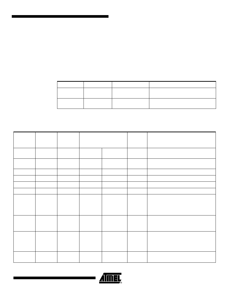
Table 6-5.
CameraLink Serial Communication Description
Signal Name
I/O
Type
Description
SerTFG
O
RS644
Differential pair for serial communication
to the frame grabber
SerTC
I
RS644
Differential pair for serial communication
from the frame grabber
Table 6-6.
Internal Register Mapping
Start Addr
(Hex)
Size
Dec)
End
Addr (Hex)
Access Type
Processing Internal Task
Factory
Settings
Description
000
1
RO
RO
Synchronization register for serial
communication (value 00)
001
1
RW
-
1
Communication speed multiplier (9600 -
115,2K): volatile register 1, 2, 3, 4, 6, 8, 12
040
51
RO
-
Hardware identifier
080
8
RO
-
Firmware identifier
0C0
51
RW
-
User identifier
100
4
RW
RW
Status (ref. Camera Status Management)
104
4
WO
-
Lock/Unlock mode: advanced user/user
1: Lock advanced user mode
(into user mode)
Unlock key value: unlock user
108
1
RO
-
Privilege level
1: Advanced user mode
2: User mode
109
1
WO
-
Current configuration save in Eeprom
1: User settings (allowed only for advanced
user mode)
2 to 4: User settings
10A
1
RW
-
0
Current configuration restore from Eeprom
1 to 4: User settings