2 ouput data timing – Rainbow Electronics ATMOS™ 1M60 User Manual
Page 10
10
5429B–IMAGE–04/05
ATMOS -1M60/1M30 [Preliminary]
• Readout of dummy frames (to prevent against large dark current integration) while the
camera waits for the next trigger event
The integration delay is a few µs. The minimum pulse duration is 1µs. The source of ITC signal
is selectable between CameraLink CC1 signal and TTL_IO trigger input. See Register Mode
Control @ 204H Internal Register Mappingon on
page 17
The period is defined by the ITC signal period.
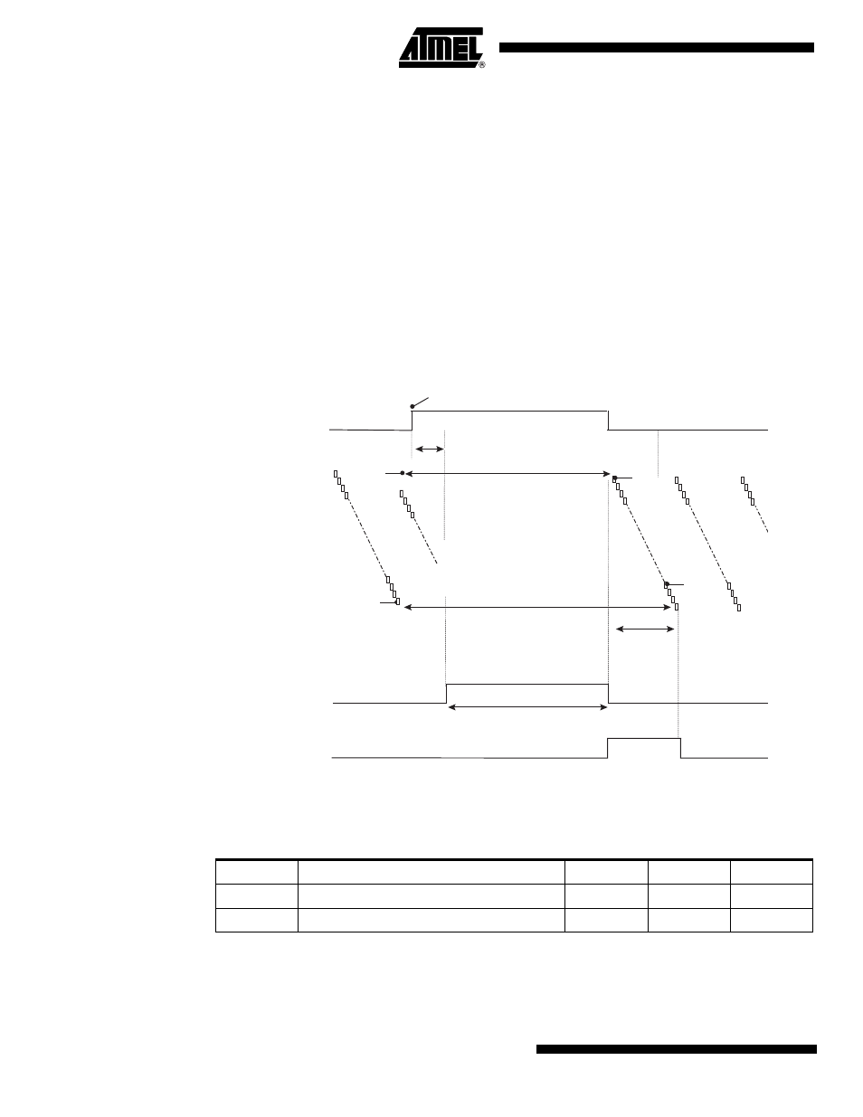
As the integration time is not the same for all lines (in the following timing diagram line n integra-
tion time is greater than line 1 integration time) this mode must be used with a pulsed light
source or a shutter element. Moreover any residual light when shutter output signal is inhibited
must be avoided. The exposure time is defined by the ITC signal high state time and all the lines
are exposed during the same time
Figure 4-5.
ITC Mode Chronogram
4.2
Ouput Data Timing
Line 1 Reset
Line 1
Integration
(Frame N)
Frame N
Readout
Line n
Integration
(Frame N)
Line n Reset
Line 1 Readout
and Reset
Trigger N Event
ITC in
Shutter Time
Shutter out
Trigger Delay
FVAL
Line n Readout
and Reset
Table 4-4.
Timing Values
Label
Description
Min
Typ
Max
Ts
Input setup to clock delay
1ns
Th
Output hold from clock delay
1ns