Rainbow Electronics MAX8514 User Manual
Page 2
MAX8513/MAX8514
Wide-Input, High-Frequency, Triple-Output Supplies
with Voltage Monitor and Power-On Reset
2
_______________________________________________________________________________________
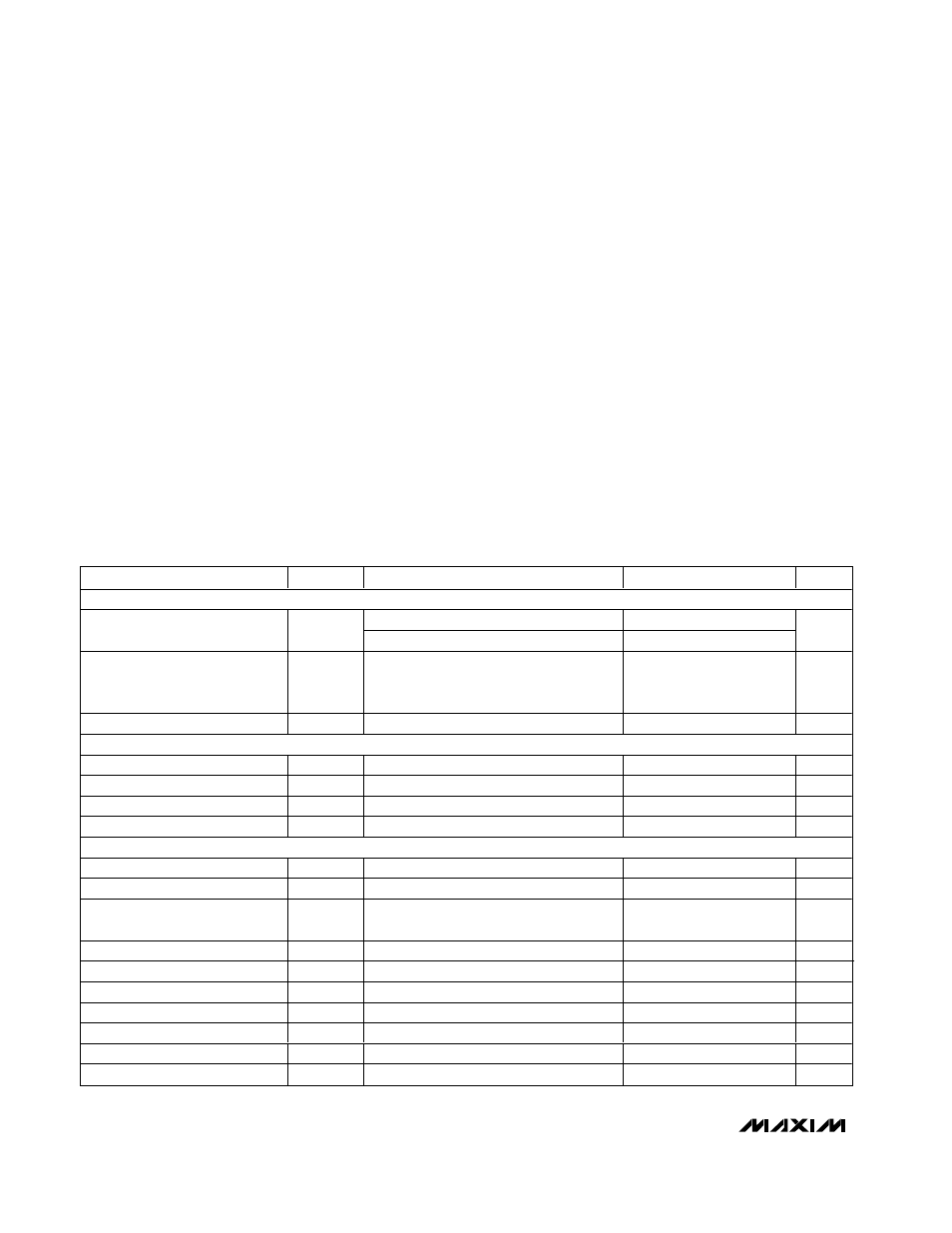
ABSOLUTE MAXIMUM RATINGS
ELECTRICAL CHARACTERISTICS
(V
IN
= V
LX
= V
SUP2
= 12V, V
PVL
= V
BST
- V
LX
= V
DRV3P
= 5V, V
SUP3N
= 3.3V, V
DRV3N
= -5V, C
VL
= 4.7µF, C
REF
= 0.22µF, R
FREQ
=
15.0kΩ,
T
A
= 0°C to +85°C
, unless otherwise noted. Typical values are at T
A
= +25°C.)
Stresses beyond those listed under “Absolute Maximum Ratings” may cause permanent damage to the device. These are stress ratings only, and functional
operation of the device at these or any other conditions beyond those indicated in the operational sections of the specifications is not implied. Exposure to
absolute maximum rating conditions for extended periods may affect device reliability.
IN, DRV3P, SUP2 to GND.......................................-0.3V to +30V
DRV2 to GND ..........................................-0.3V to (V
SUP2
+ 0.3V)
DRV3N to GND......................(V
SUP3N
- 28V) to (V
SUP3N
+ 0.3V)
FREQ, PFI, PFO, POR, SUP3N, SYNC/EN,
CSP, CSN to GND ................................................-0.3V to +6V
VL to GND ...................-0.3V to the lesser of (V
IN
+ 0.3V) or +6V
COMP1, FB1, FB2, FB3P, FB3N, REF, ILIM,
SS, SEQ to GND......................................-0.3V to (V
VL
+ 0.3V)
PVL to PGND ............................................................-0.3V to +6V
DL to PGND...............................................-0.3V to (V
PVL
+ 0.3V)
BST to LX..................................................................-0.3V to +6V
DH to LX ....................................................-0.3V to (V
BST
+ 0.3V)
PGND to GND .......................................................-0.3V to +0.3V
VL Short Circuit to GND .............................................Continuous
Continuous Power Dissipation (T
A
= +70°C)
28-Pin QSOP (derate 10.8mW/°C above +70°C).........860mW
Operating Temperature Range
MAX8513EEI, MAX8514EEI .............................-40°C to +85°C
MAX8514AEI..................................................-40°C to +125°C
Junction Temperature ......................................................+150°C
Storage Temperature Range .............................-65°C to +150°C
Lead Temperature (soldering, 10s) .................................+300°C
PARAMETER
SYMBOL
CONDITIONS
MIN
TYP
MAX
UNITS
GENERAL
5.5
28.0
IN Operating Range
IN = VL
4.5
5.5
V
IN Supply Current
V
FB1
= 1.3V, V
FB2
= V
FB3
= 1.0V, does not
include switching current to PVL and BST,
SYNC/EN = VL
2.6
3.2
mA
IN Shutdown Current
V
SYNC/EN
= 0, R
FREQ
= 50k
Ω
200
300
µA
VL REGULATOR
VL Output Voltage
V
IN
= 6V to 28V, I
VL
= 0.1mA to 40mA
4.75
5
5.25
V
VL Dropout Voltage
From IN to VL, V
IN
= 5V, I
VL
= 40mA
560
mV
VL Line Regulation
V
IN
= 6V to 28V, I
VL
= 5mA
0.05
%
VL Undervoltage Threshold
VL rising, V
HYST
= 675mV (typ)
3.6
4.2
V
OUT1 (BUCK CONVERTER)
Output Voltage Range
V
OUT1
(Note 1)
1.25
5.50
V
FB1 Regulation Threshold
V
FB1
1.234
1.25
1.259
V
Error-Amplifier Open-Loop
Voltage Gain
A
VOL
65
90
dB
FB1 Input Bias Current
I
FB1_BIAS
V
FB1
= 1.3V
-200
+10
+200
nA
Error-Amplifier Gain Bandwidth
25
MHz
DH Output-Resistance High
R
DH_HIGH
1.5
2.55
Ω
DH Output-Resistance Low
R
DH_LOW
1.2
2.1
Ω
DL Output-Resistance High
R
DL_HIGH
2.5
5
Ω
DL Output-Resistance Low
R
DL_LOW
0.7
1.3
Ω
Driver Dead Time
t
dt
Starts from V
DL
= 1V or (V
DH
- V
LX
) = 1V
50
ns