0v supply ac electrical characteristics – Rainbow Electronics MAX19999 User Manual
Page 3
MAX19999
Dual, SiGe High-Linearity, 3000MHz to
4000MHz Downconversion Mixer with LO Buffer
_______________________________________________________________________________________
3
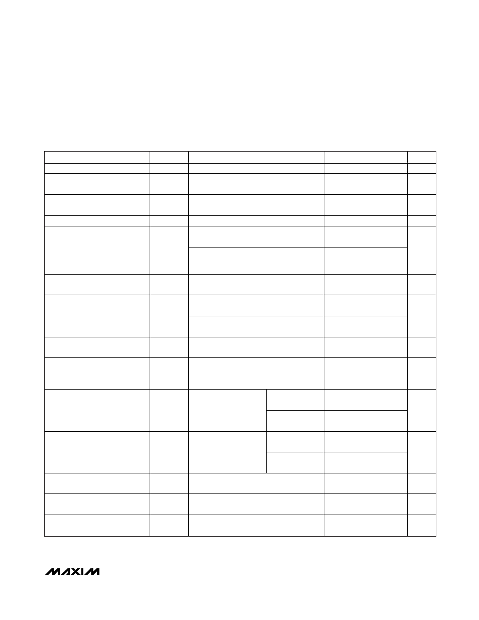
PARAMETER
SYMBOL
CONDITIONS
MIN
TYP
MAX
UNITS
Conversion Gain
G
C
T
C
= +25°C (Notes 6, 9)
7.3
8.3
9.3
dB
Conversion Gain Flatness
f
RF
= 3200MHz to 3900MHz, over any
100MHz band
0.15
dB
Gain Variation Over Temperature
TC
CG
f
RF
= 3200MHz to 3900MHz, T
C
= -40°C to
+85°C
-0.01
dB/°C
Input Compression Point
IP
1dB
(Notes 6, 9, 10)
9.8
11.4
dBm
f
RF1
- f
RF2
= 1MHz, P
RF
= -5dBm per tone
(Notes 6, 9)
21.6
24.3
Third-Order Input Intercept Point
IIP3
f
RF
= 3550MHz, f
RF1
- f
RF2
= 1MHz,
P
RF
= -5dBm per tone, T
C
= +25°C
(Notes 6, 9)
22
24.3
dBm
Third-Order Input Intercept Point
Variation Over Temperature
f
RF1
- f
RF2
= 1MHz, T
C
= -40°C to +85°C
±0.3
dBm
Single sideband, no blockers present
(Notes 5, 6)
10.5
13
Noise Figure
NF
SSB
Single sideband, no blockers present,
f
RF
= 3500MHz, T
C
= +25°C (Notes 5, 6)
10.5
11.5
dB
Noise Figure Temperature
Coefficient
TC
NF
Single sideband, no blockers present,
T
C
= -40°C to +85°C
0.018
dB/°C
Noise Figure Under Blocking
Conditions
NF
B
f
BLOC KE R
= 3700M H z, P
BLOC KE R
= 8d Bm,
f
RF
= 3450M H z, f
LO
= 3100M H z, P
LO
= 0d Bm,
V
C C
= 5.0V, T
C
= + 25°C ( Notes 5, 6, 11)
21
25
dB
P
RF
= -10dBm,
(Notes 5, 6)
68
74
2RF-2LO Spurious Rejection
2 x 2
f
RF
= 3500MHz, f
LO
=
3150MHz, f
SPUR
= f
LO
+
175MHz, T
C
= +25°C
P
RF
= -5dBm,
(Notes 6, 9)
63
69
dBc
P
RF
= -10dBm,
(Notes 5, 6)
77
86
3RF-3LO Spurious Rejection
3 x 3
f
RF
= 3500MHz, f
LO
=
3150MHz, f
SPUR
= f
LO
+
116.67MHz, T
C
= +25°C
P
RF
= -5dBm,
(Notes 6, 9)
67
76
dBc
RF Input Return Loss
LO on and IF terminated into a matched
impedance
15.4
dB
LO Input Return Loss
RF and IF terminated into a matched
impedance
14
dB
IF Output Impedance
Z
IF
Nominal differential impedance at the IC’s
IF outputs
200
Ω
+5.0V SUPPLY AC ELECTRICAL CHARACTERISTICS
(
Typical Application Circuit, V
CC
= +4.75V to +5.25V, RF and LO ports are driven from 50
Ω sources, P
LO
= -3dBm to +3dBm,
P
RF
= -5dBm, f
RF
= 3200MHz to 3900MHz, f
LO
= 2800MHz to 3600MHz, f
IF
= 350MHz, f
RF
> f
LO
, T
C
= -40°C to +85°C. Typical val-
ues are at V
CC
= +5.0V, P
RF
= -5dBm, P
LO
= 0dBm, f
RF
= 3550MHz, f
LO
= 3200MHz, f
IF
= 350MHz, T
C
= +25°C, unless otherwise
noted.) (Note 8)