Operating range, Operating precautions, Operating conditions – Rainbow Electronics TH7899M User Manual
Page 7: Th7899m
7
TH7899M
2201A–IMAGE–02/02
Operating Range
Operating range defines the limits between which the functioning is guaranteed.
Electrical limits of applied signals are given in the operating condition section.
Operating
Precautions
Shorting one of the video outputs to one of the input pins even temporarily, can perma-
nently damage the output amplifier.
Due to MPP mode or negative voltages, image zone clocks and readout registers do not
include ESD protection. To avoid degradation, the TH7899M device should be handled
with a grounded bracelet and stored on a conductive layer used for shipment.
Operating Conditions
See “Pin-out/Pin Designation” on page 23.
Note:
1. V
G L
= 12V and V
DR
= 15V is only when using a summing mode to optimize saturation level.
The reference level (V
S
) of an unused output amplifier can be disconnected to avoid the consumption of this amplifier.
Maximum Applied Voltage
Pins A3 A8 A13 A14 B3 B13 G1 G15 J1 J15 P3 P8 P13 R2 R3 R8 R13
0V (ground)
Maximum voltage applied (VGB) with respect to the substrate VSS
Pins B5 B4 P12 P11 P4 P5 P6 P7 B12 B11 B10 B9 H15 H1 R6 R5 A10 A11 A5 A4 R12 R11 R4
R7 A9 A12 R1
|VGB| = 15V
Pins B6 A6 B7 A7 P9 R9 P10 R10
|VGB| = 12V
Pins R1 R15 A1 A15 A2 R14 P2 P14 B2 B14 P1 P15 B1 B15 K1 K15 F1 F15 L1 L15 E1 E15
VGB = -0.3 to 15.5V
Pins M1 M15 D1 D15
VGB = -0.3 to 12V
Maximum voltage difference
∆
V between two pins of each group
Pin group: R6 R5 P4 P5 P6 P7 H1 R4 R7
|
∆
V| =15V
Pin group: A10 A11 B12 B11 B10 B9 H15 A9 A12
|
∆
V| =15V
Pin group: B5 B6 A5 A6 B4 B7 A4 A7 P12 P9 R12 R9 P11 P10 R11 R10 H1 H15
|
∆
V| =15V
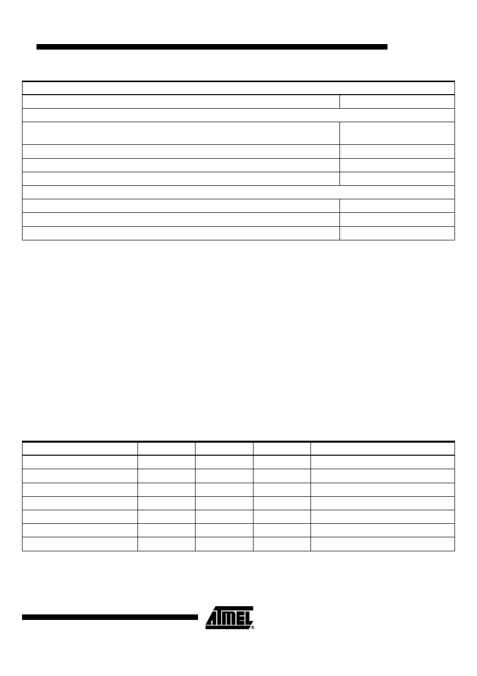
Table 1. DC Characteristics
Parameter
Min.
Typ.
Max.
Notes
V
S (1 to 4)
0V
V
DD (1 to 4)
14.5V
15V
15.5V
V
SS
0V
0V
V
GS (1 to 4)
3.7
4V
4.3V
2V for MPP mode (option)
V
DR (1 to 4)
13V/14.5V
13.5V/15V
14V/15.5V
V
DE (A and B)
5.5V
6V
6.5V
V
GL (1 to 4)
0.7V/11.7V
1V/12V
1.3V/12.3V
0V/12V for MPP mode (option)