Timing diagram, Full frame timing diagram (without memory zone), Th7899m – Rainbow Electronics TH7899M User Manual
Page 10
10
TH7899M
2201A–IMAGE–02/02
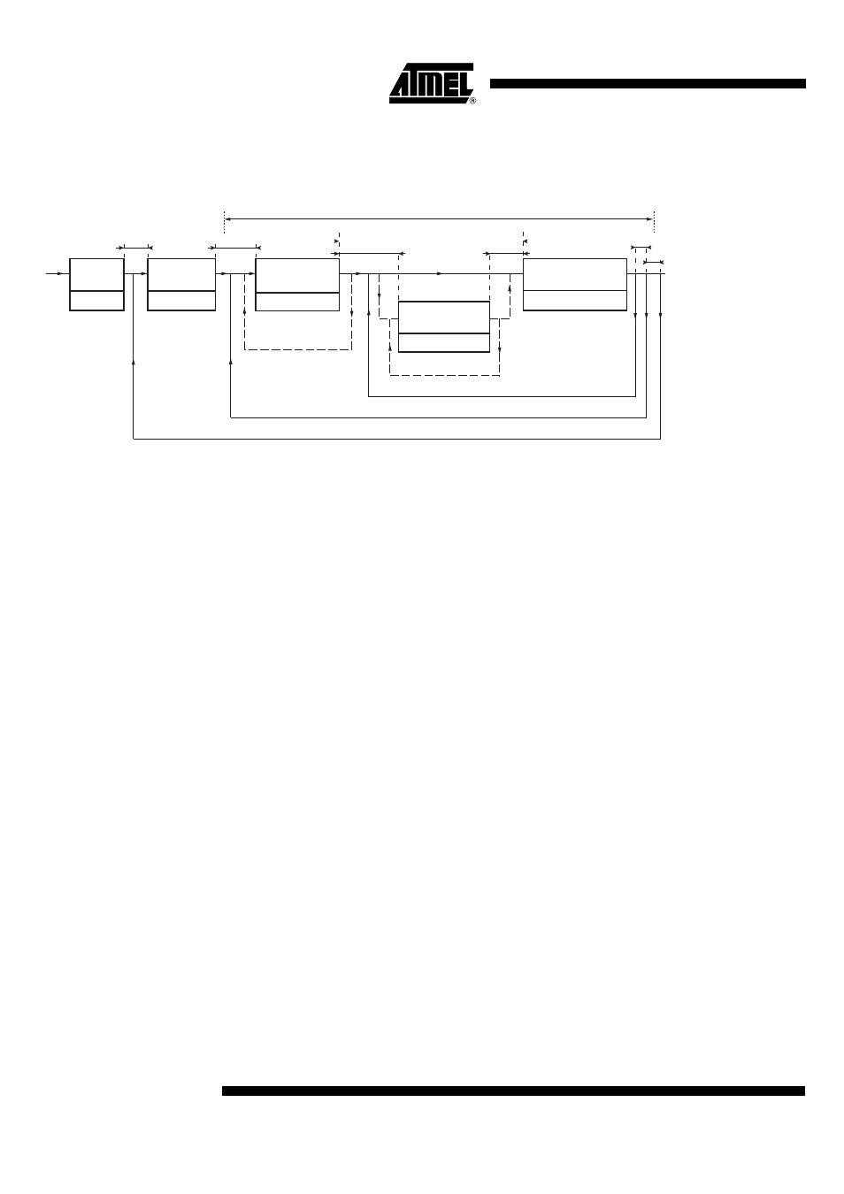
Timing Diagram
Full Frame Timing Diagram (Without Memory Zone)
Summation options:
vs = number of vertical summation (vs = 1 to sum 2 lines in the readout register),
hs = number of horizontal summation (hs = 0 to sum 2 pixels in the
φ
S gate, only add the
timing diagram once of figure 10),
vnb and hnb are defined according to the chosen operating mode in “” on page 9.
Note:
1. Cleaning period consists of emptying the image zone of all charges created by ther-
mal generation. To achieve such cleaning, the readout time Treadout defined in the
above diagram shall be used. Nevertheless, it is possible to reduce cleaning time of
the image zone by accumulating several lines in the output register (Figure 7) before
reading out the resulting signal (Figure 9). The number of accumulated lines is limited
by the readout register saturation level.
Cleaning
period
see note 1
Exposure
time
see figure 5
Horizontal
summation
see figure 7
100 ns min
100 ns min
100 ns min
no delay
100 ns min
Vertical tranfer
of one line
see figure 6
Horizontal transfer of
one pixel / readout
The video line comprises:
·
18 inactive prescans
·
7 dark references
·
5 isolation elements
·
2048 useful pixels (1 output)
or 1024 useful pixels
(2 or 4 outputs)
see figure 8
x hnb/(hs+2) minimum
x vnb/(vs+1) minimum (can be continued until exposure time signal appears)
return to exposure time as soon as vnb (vs+1) min vertical transfers are over or when exposure time signal is clocked
x vs
x hs
Readout time T
readout
100 ns min
100 ns min