Pin description – Rainbow Electronics MAX8742 User Manual
Page 9
MAX8741/
M
AX8742
500kHz Multi-Output Power-Supply Controllers
with High Impedance in Shutdown
_______________________________________________________________________________________
9
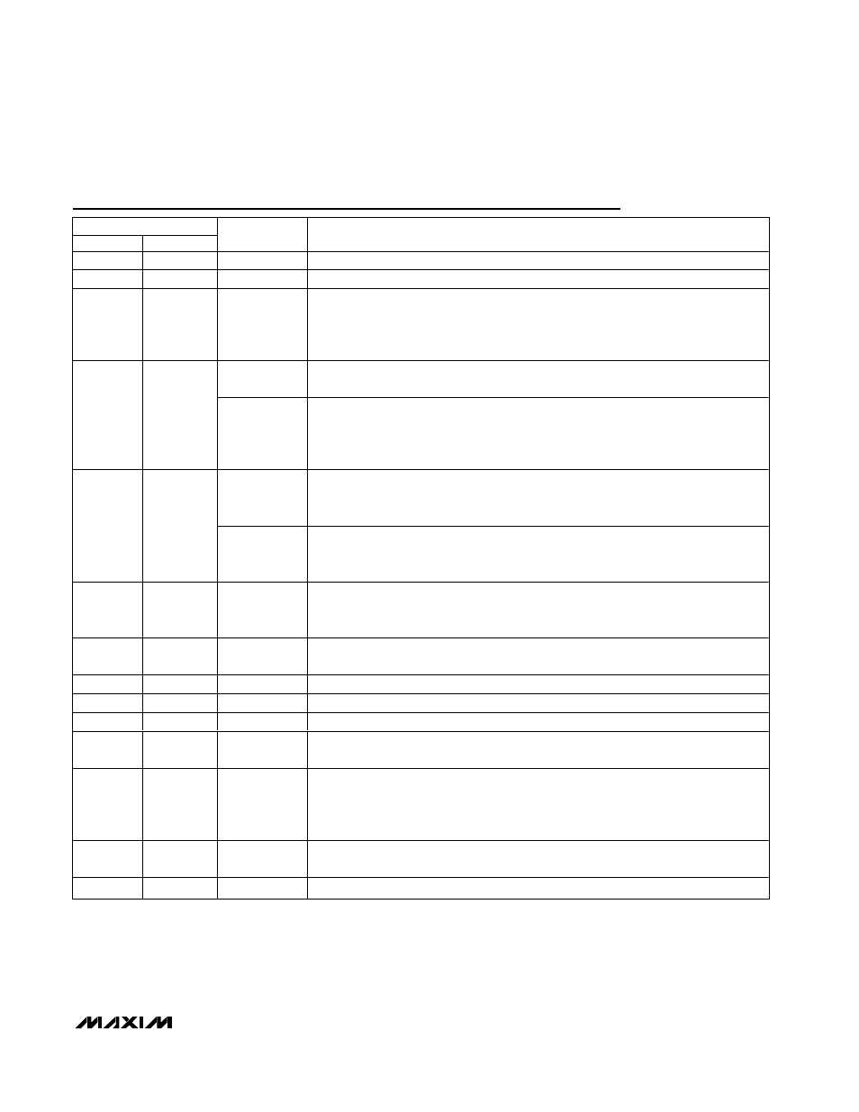
Pin Description
PIN
SSOP
TQFN
NAME
FUNCTION
1
29
CSH3
Current-Sense Input for the 3.3V SMPS. Current-limit level is 100mV referred to CSL3.
2
30
CSL3
Current-Sense Input. Also serves as the feedback input in fixed-output mode.
3
31
FB3
Feedback Input for the 3.3V SMPS. Regulates at FB3 = REF (approximately 2.5V) in
adjustable mode. FB3 is a dual-mode input that also selects the 3.3V fixed output-
voltage setting when connected to GND. Connect FB3 to a resistor-divider for
adjustable-output mode.
12OUT
(MAX8742)
12V/120mA Linear-Regulator Output. Input supply comes from V
DD
. Bypass 12OUT to
GND with 1µF (min).
4
1
STEER
(MAX8741)
Logic-Control Input for Secondary Feedback. Selects the PWM that uses a transformer
and secondary feedback signal (SECFB):
STEER = GND: 3.3V SMPS uses transformer
STEER = V
L
: 5V SMPS uses transformer
V
DD
(MAX8742)
Supply Voltage Input for the 12OUT Linear Regulator. Also connects to an internal
resistor-divider for secondary winding feedback and to an 18V overvoltage shunt
regulator clamp.
5
2
SECFB
(MAX8741)
Secondary Winding Feedback Input. Normally connected to a resistor-divider from an
auxiliary output. SECFB regulates at V
SECFB
= 2.5V (see the Secondary Feedback
Regulation Loop section). Connect to V
L
if not used.
6
3
SYNC
Oscillator Synchronization and Frequency Select. Connect to V
L
for 500kHz operation;
connect to GND for 333kHz operation. Can be driven at 400kHz to 583kHz for external
synchronization.
7
4
TIME/ON5
Dual-Purpose Timing Capacitor Pin and ON/OFF Control Input. See the Power-Up
Sequencing and ON/
OFF
Controls section.
8
5
GND
Low-Noise Analog Ground and Feedback Reference Point
9
7
REF
2.5V Reference Voltage Output. Bypass to GND with 1µF (min).
10
8
SKIP
Log i c- C ontr ol Inp ut that D i sab l es Id l e M od e w hen H i g h. C onnect to G N D for nor m al use.
11
9
RESET
Active-Low Timed Reset Output. RESET swings GND to V
L
. Goes high after a fixed
32,000 clock-cycle delay following power-up.
12
10
FB5
Feedback Input for the 5V SMPS. Regulates at FB5 = REF (approximately 2.5V) in
adjustable mode. FB5 is a dual-mode input that also selects the 5V fixed output-
voltage setting when connected to GND. Connect FB5 to a resistor-divider for
adjustable-output mode.
13
11
CSL5
C ur r ent- S ense Inp ut for the 5V S M P S . Al so ser ves as the feed b ack i np ut i n fi xed - outp ut
m od e, and as the b ootstr ap sup p l y i np ut w hen the vol tag e on C S L5/V
L
i s > 4.5V .
14
12
CSH5
Current-Sense Input for the 5V SMPS. Current-limit level is 100mV referred to CSL5.