Design procedure – Rainbow Electronics MAX8742 User Manual
Page 20
MAX8741/
M
AX8742
500kHz Multi-Output Power-Supply Controllers
with High Impedance in Shutdown
20
______________________________________________________________________________________
voltage. A linear postregulator may still be needed to
meet strict output-accuracy specifications.
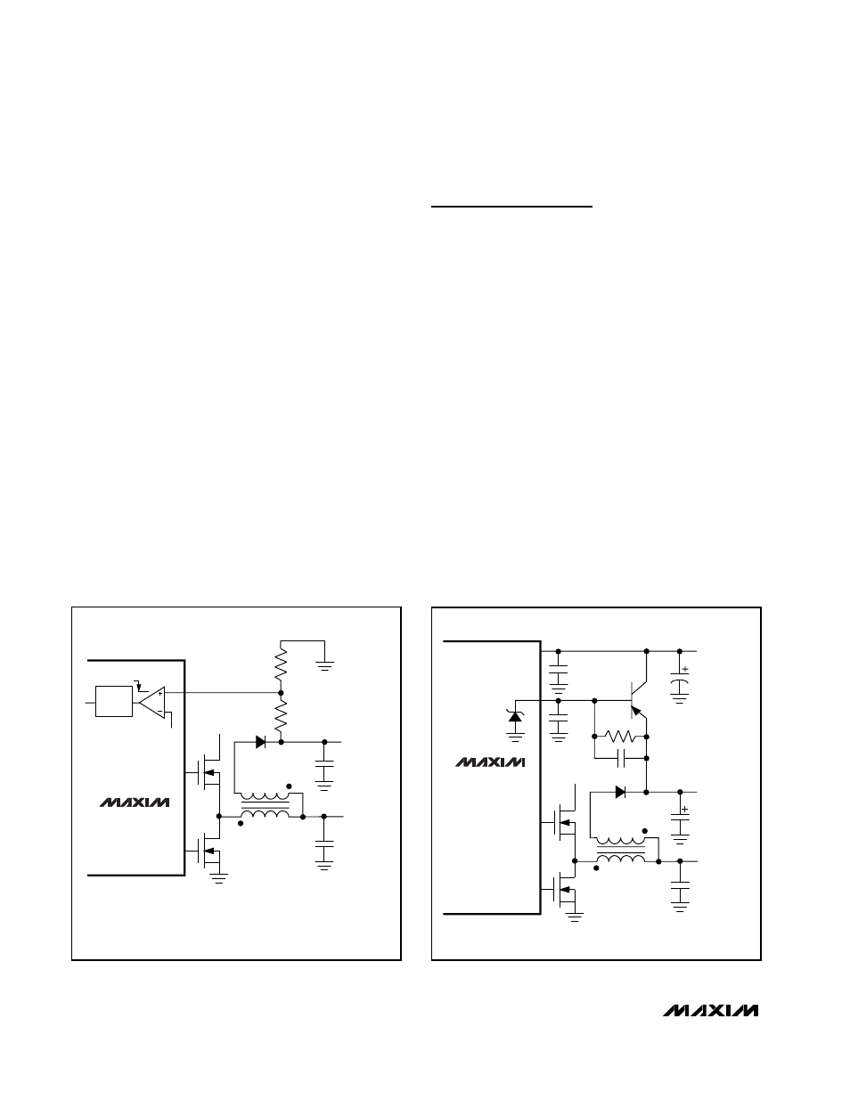
The MAX8742 has a V
DD
pin that regulates at a fixed
13.5V, set by an internal resistor-divider. The MAX8741
has an adjustable secondary-output voltage set by an
external resistor-divider on SECFB (Figure 5). Ordinarily,
the secondary regulation point is set 5% to 10% below
the voltage normally produced by the flyback effect. For
example, if the output voltage as determined by turns
ratio is 15V, set the feedback resistor ratio to produce
13.5V. Otherwise, the SECFB one-shot might be triggered
unintentionally, unnecessarily increasing supply current
and output noise.
12V Linear-Regulator Output (MAX8742)
The MAX8742 includes a 12V linear-regulator output
capable of delivering 120mA of output current.
Typically, greater current is available at the expense of
output accuracy. If an accurate output of more than
120mA is needed, an external pass transistor can be
added. The circuit in Figure 6 delivers more than
200mA. Total output current is constrained by the V+
input voltage and the transformer primary load (see the
Maximum V
DD
Output Current vs. Input Voltage graphs
in the Typical Operating Characteristics).
Design Procedure
The three predesigned 3V/5V standard application cir-
cuits (Figure 1 and Table 1) contain ready-to-use solu-
tions for common application needs. Also, one
standard flyback transformer circuit supports the
12OUT linear regulator in the Applications Information
section. Use the following design procedure to optimize
these basic schematics for different voltage or current
requirements. Before beginning a design, however,
firmly establish the following:
•
Maximum Input (Battery) Voltage, V
IN(MAX)
. This
value should include the worst-case conditions,
such as no-load operation when a battery charger or
AC adapter is connected but no battery is installed.
V
IN(MAX)
must not exceed 30V.
•
Minimum Input (Battery) Voltage, V
IN(MIN)
.This
should be taken at full load under the lowest battery
conditions. If V
IN(MIN)
is less than 4.2V, use an exter-
nal circuit to externally hold V
L
above the V
L
undervolt-
age- lockout threshold. If the minimum input-output
difference is less than 1.5V, the filter capacitance
required to maintain good AC load regulation increas-
es (see the Low-Voltage Operation section).
MAX8741
POSITIVE
SECONDARY
OUTPUT
MAIN
OUTPUT
DH_
V+
SECFB
2.5V REF
R2
R1
1-SHOT
TRIG
DL_
WHERE V
REF
(NOMINAL) = 2.5V
+V
TRIP
= V
REF
(
1 + –––
)
R1
R2
MAX8742
V
DD
OUTPUT
12V OUTPUT
200mA
MAIN
OUTPUT
2N3906
0.1µF
0.1µF
0.1µF
2.2µF
10µF
10Ω
V+
V
DD
12OUT
DH_
DL_
Figure 5. Adjusting the Secondary Output Voltage with SECFB
Figure 6. Increased 12V Linear-Regulator Output Current