Rainbow Electronics MAX8742 User Manual
Page 2
MAX8741/
M
AX8742
500kHz Multi-Output Power-Supply Controllers
with High Impedance in Shutdown
2
_______________________________________________________________________________________
ABSOLUTE MAXIMUM RATINGS
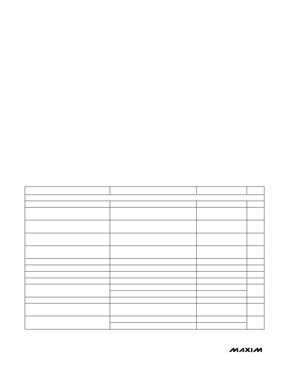
ELECTRICAL CHARACTERISTICS
(V+ = 15V, both PWMs on, SYNC = V
L
, V
L
load = 0, REF load = 0, SKIP = 0,
T
A
= 0°C to +85°C
, unless otherwise noted. Typical
values are at T
A
= +25°C.)
Stresses beyond those listed under “Absolute Maximum Ratings” may cause permanent damage to the device. These are stress ratings only, and functional
operation of the device at these or any other conditions beyond those indicated in the operational sections of the specifications is not implied. Exposure to
absolute maximum rating conditions for extended periods may affect device reliability.
V+ to GND ..............................................................-0.3V to +36V
PGND to GND.....................................................................±0.3V
V
L
to GND ................................................................-0.3V to +6V
BST3, BST5 to GND ..............................................-0.3V to +36V
CSH3, CSH5 to GND................................................-0.3V to +6V
FB3 to GND ..............................................-0.3V to (CSL3 + 0.3V)
FB5 to GND ...............................................-0.3V to (CSL5 +0.3V)
LX3 to BST3..............................................................-6V to +0.3V
LX5 to BST5..............................................................-6V to +0.3V
REF, SYNC, SEQ, STEER, SKIP,
TIME/ON5, SECFB, RESET to GND ..........-0.3V to (V
L
+ 0.3V)
V
DD
to GND. ...........................................................-0.3V to +20V
RUN/ON3, SHDN to GND.............................-0.3V to (V+ + 0.3V)
12OUT to GND ..........................................-0.3V to (V
DD
+ 0.3V)
DL3, DL5 to PGND. .......................................-0.3V to (V
L
+ 0.3V)
DH3 to LX3 ..............................................-0.3V to (BST3 + 0.3V)
DH5 to LX5 ..............................................-0.3V to (BST5 + 0.3V)
V
L
, REF Short to GND ................................................Momentary
12OUT Short to GND..................................................Continuous
REF Current...........................................................+5mA to -1mA
V
L
Current. ........................................................................+50mA
12OUT Current . .............................................................+200mA
V
DD
Shunt Current. ...........................................................+15mA
Continuous Power Dissipation (T
A
= +70°C)
28-Pin SSOP (derate 9.52mW/°C above +70°C) ........762mW
32-Pin Thin QFN (derate 21.3mW/°C above +70°C) ....1702mW
Operating Temperature Range ...........................-40°C to +85°C
Storage Temperature Range ............................-65°C to +160°C
Lead Temperature (soldering, 10s) ................................+300°C
PARAMETER
CONDITIONS
MIN
TYP
MAX
UNITS
MAIN SMPS CONTROLLERS
Input Voltage Range
4.2
30.0
V
3V Output Voltage in Adjustable Mode
V+ = 4.2V to 30V, CSH3 - CSL3 = 0,
CSL3 connected to FB3
2.42
2.5
2.58
V
3V Output Voltage in Fixed Mode
V+ = 4.2V to 30V, 0 < CSH3 - CSL3
< 80mV, FB3 = 0
3.20
3.39
3.47
V
5V Output Voltage in Adjustable Mode
V+ = 4.2V to 30V, CSH5 - CSL5 = 0,
CSL5 connected to FB5
2.42
2.5
2.58
V
5V Output Voltage in Fixed Mode
V+ = 5.3V to 30V, 0 < CSH5 - CSL5
< 80mV, FB5 = 0
4.85
5.13
5.25
V
Output Voltage Adjust Range
Either SMPS
REF
5.5
V
Adjustable-Mode Threshold Voltage
Dual-mode comparator
0.5
1.1
V
Load Regulation
Either SMPS, 0 < CSH_ - CSL_ < 80mV
-2
%
Line Regulation
Either SMPS, 5.2V < V+ < 30V
0.03
%/V
CSH3 - CSL3 or CSH5 - CSL5
80
100
120
Current-Limit Threshold
SKIP = V
L
or V
DD
< 13V or SECFB < 2.44V
-50
-100
-150
mV
Idle-Mode Threshold
SKIP = 0, not tested
10
25
40
mV
Soft-Start Ramp Time
From enable to 95% full current limit with
respect to f
OSC
(Note 1)
512
Clks
SYNC = V
L
450
500
550
Oscillator Frequency
SYNC = 0
283
333
383
kHz