Standard application circuit, Detailed description – Rainbow Electronics MAX8742 User Manual
Page 12
MAX8741/
M
AX8742
500kHz Multi-Output Power-Supply Controllers
with High Impedance in Shutdown
12
______________________________________________________________________________________
Standard Application Circuit
The basic MAX8741 dual-output 3.3V/5V buck converter
(Figure 1) is easily adapted to meet a wide range of
applications with inputs up to 28V by substituting com-
ponents from Table 1. These circuits represent a good
set of tradeoffs between cost, size, and efficiency,
while staying within the worst-case specification limits
for stress-related parameters, such as capacitor ripple
current. Do not change the frequency of these circuits
without first recalculating component values (particularly
inductance value at maximum battery voltage). Adding
a Schottky rectifier across each synchronous rectifier
improves the efficiency of these circuits by approxi-
mately 1%, but this rectifier is otherwise not needed
because the MOSFETs required for these circuits typi-
cally incorporate a high-speed silicon diode from drain
to source. Use a Schottky rectifier rated at a DC current
equal to at least one-third of the load current.
Detailed Description
The MAX8741/MAX8742 are dual, BiCMOS, switch-
mode power-supply controllers designed primarily for
buck-topology regulators in battery-powered applica-
tions where high-efficiency and low-quiescent supply
current are critical. Light-load efficiency is enhanced by
automatic idle-mode operation, a variable-frequency
pulse-skipping mode that reduces transition and gate-
charge losses. Each step-down, power-switching cir-
cuit consists of two n-channel MOSFETs, a rectifier,
and an LC output filter. The output voltage is the aver-
age AC voltage at the switching node, which is regulat-
ed by changing the duty cycle of the MOSFET
switches. The gate-drive signal to the n-channel high-
side MOSFET must exceed the battery voltage, and is
provided by a flying-capacitor boost circuit that uses a
100nF capacitor connected to BST_.
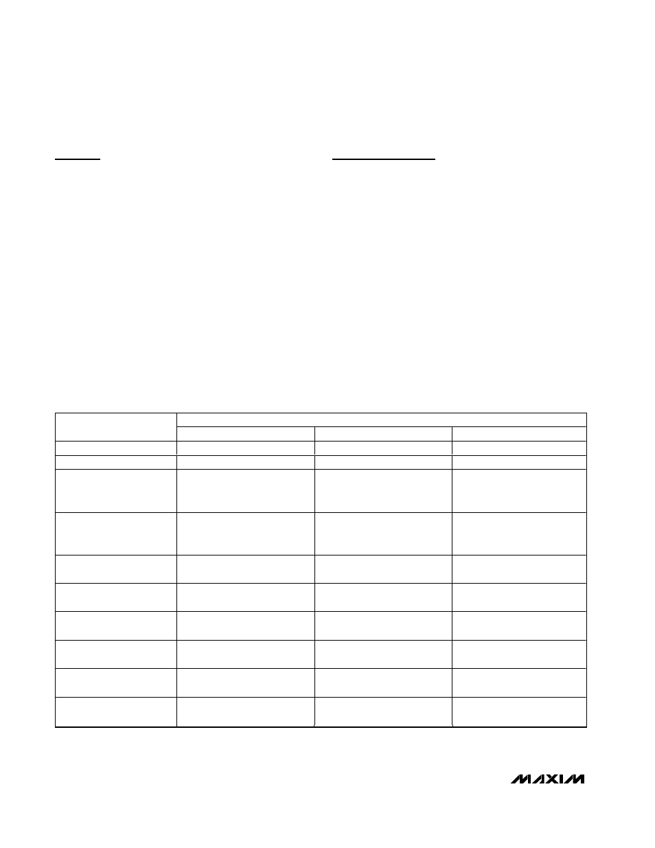
Table 1. Component Selection for Standard 3.3V/5V Application
LOAD CURRENT
COMPONENT
4A/333kHz
4A/500kHz
6A/500kHz
Input Range
7V to 24V
7V to 24V
7V to 24V
Frequency
333kHz
500kHz
500kHz
Q1, Q3 High-Side
MOSFETs
1/2 Fairchild FDS6982S or
1/2 International Rectifier
IRF7901D1
1/2 Fairchild FDS6982S or
1/2 International Rectifier
IRF7901D1
Fairchild FDS6612A or
International Rectifier
IRF7807V
Q2, Q4 Low-Side
MOSFETs with Integrated
Schottky Diodes
1/2 Fairchild FDS6982S or
1/2 International Rectifier
IRF7901D1
1/2 Fairchild FDS6982S or
1/2 International Rectifier
IRF7901D1
Fairchild FDS6670S or
International Rectifier
IRF7807DV1
C3 Input Capacitor
3 x 10µF, 25V ceramic
Taiyo Yuden TMK432BJ106KM
3 x 10µF, 25V ceramic
Taiyo Yuden TMK432BJ106KM
4 x 10µF, 25V ceramic
Taiyo Yuden TMK432BJ106KM
C1 Output Capacitor
150µF, 6V POSCAP
Sanyo 6TPC150M
150µF, 6V POSCAP
Sanyo 6TPC150M
2 x 150µF, 6V POSCAP
Sanyo 6TPC150M
C2 Output Capacitor
2 x 150µF, 4V POSCAP
Sanyo 4TPC150M
2 x 150µF, 4V POSCAP
Sanyo 4TPC150M
2 x 220µF, 4V POSCAP
Sanyo 4TPC220M
R1, R2 Resistors
0.018
Ω
Dale WSL2512-R018-F
0.018
Ω
Dale WSL2512-R018-F
0.012
Ω
Dale WSL2512-R012-F
L1 Inductor
10µH, 4.5A Ferrite
Sumida CDRH124-100
7.0µH, 5.2A Ferrite
Sumida CEI122-H-7R0
4.2µH, 6.9A Ferrite
Sumida CEI122-H-4R2
L2 Inductor
7.0µH, 5.2A Ferrite
Sumida CEI122-H-7R0
5.6µH, 5.2A Ferrite
Sumida CEI122-H-5R6
4.2µH, 6.9A Ferrite
Sumida CEI122-H-4R2