Pin description (continued) – Rainbow Electronics MAX8742 User Manual
Page 10
MAX8741/
M
AX8742
500kHz Multi-Output Power-Supply Controllers
with High Impedance in Shutdown
10
______________________________________________________________________________________
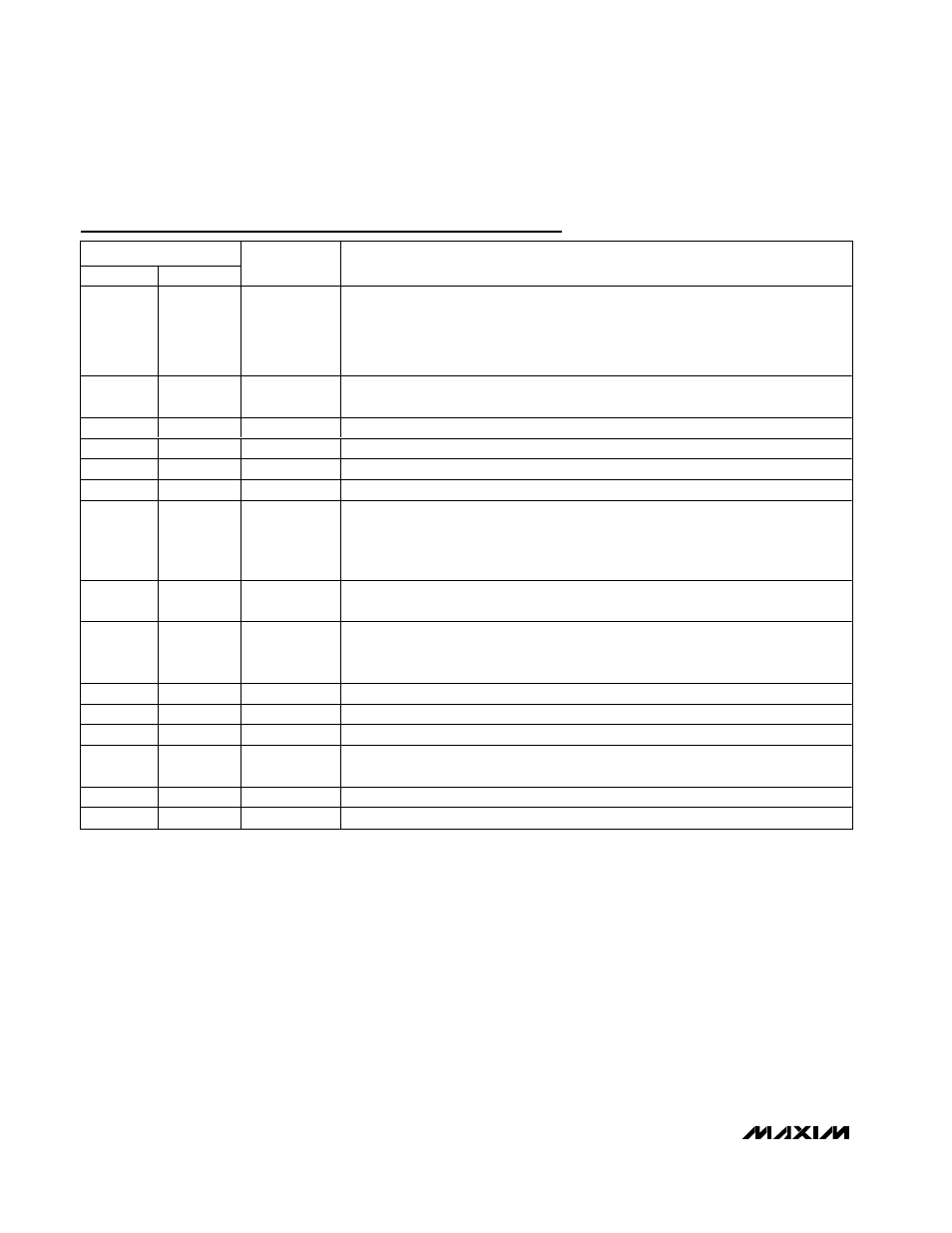
Pin Description (continued)
PIN
SSOP
TQFN
NAME
FUNCTION
15
13
SEQ
Pin-Strap Input that Selects the SMPS Power-Up Sequence:
SEQ = GND: 5V before 3.3V, RESET output determined by both outputs
SEQ = REF: Separate ON3/ON5 controls, RESET output determined by 3.3V
output
SEQ = V
L
: 3.3V before 5V, RESET output determined by both outputs
16
14
DH5
Gate-Drive Output for the 5V, High-Side N-Channel Switch. DH5 is a floating driver
output that swings from LX5 to BST5, riding on the LX5 switching-node voltage.
17
15
LX5
Switching-Node (Inductor) Connection. Can swing 2V below ground without hazard.
18
17
BST5
Boost Capacitor Connection for High-Side Gate Drive (0.1µF)
19
18
DL5
Gate-Drive Output for the Low-Side Synchronous-Rectifier MOSFET. Swings 0 to V
L
.
20
19
PGND
Power Ground
21
20
V
L
5V Internal Linear-Regulator Output. V
L
is also the supply-voltage rail for the chip.
After the 5V SMPS output has reached 4.5V (typ), V
L
automatically switches to the
output voltage through CSL5 for bootstrapping. Bypass to GND with 4.7µF. V
L
supplies up to 25mA for external loads.
22
21
V+
Battery Voltage Input, 4.2V to 30V. Bypass V+ to PGND close to the IC with a 0.22µF
capacitor. Connects to a linear regulator that powers V
L
.
23
22
SHDN
Shutdown Control Input, Active Low. Logic threshold is set at approximately 1V. For
automatic startup, connect SHDN to V+ through a 220kΩ resistor and bypass SHDN to
GND with a 0.01µF capacitor.
24
23
DL3
Gate-Drive Output for the Low-Side Synchronous-Rectifier MOSFET. Swings 0 to VL.
25
24
BST3
Boost Capacitor Connection for High-Side Gate Drive (0.1µF)
26
26
LX3
Switching-Node (Inductor) Connection. Can swing 2V below ground without hazard.
27
27
DH3
Gate-Drive Output for the 3.3V, High-Side N-Channel Switch. DH3 is a floating driver
output that swings from LX3 to BST3, riding on the LX3 switching-node voltage.
28
28
RUN/ON3
ON/OFF Control Input. See the Power-Up Sequencing and ON/
OFF
Controls section.
—
6, 16, 25, 32
N.C.
No Connection