Table 8. output mode control register, Table 9. output modes, Table 7. volume control settings (continued) – Rainbow Electronics MAX9796 User Manual
Page 23
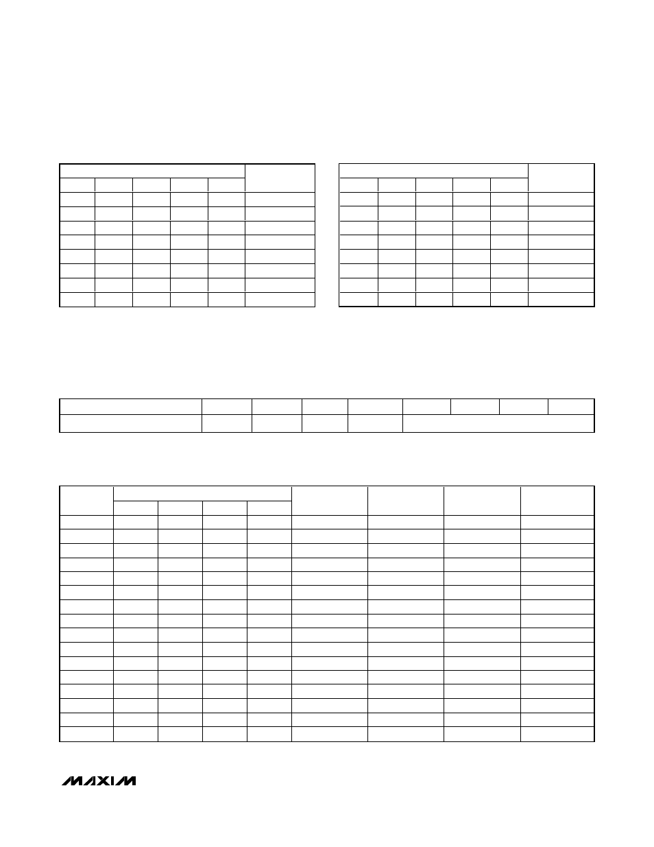
Output Mode Control
MONO+6dB in the Output Mode Control register allows
an extra 6dB of gain on the internal mono signal:
1 = Additional 6dB of gain is applied to the internal
Mono (M) signal path.
0 = No additional gain is applied to the Internal Mono
(M) signal path.
The MAX9796 has four output amplifiers: a mono
receiver amplifier, a stereo DirectDrive headphone
amplifier, and one mono Class D amplifier.
MAX9796
2.3W, High-Power Class D Audio Subsystem
with DirectDrive Headphone Amplifiers
______________________________________________________________________________________
23
B7
B6
B5
B4
B3
B2
B1
B0
Output Mode Control
1
0
0
Mono+6dB
OUTMODE (Table 9)
Table 8. Output Mode Control Register
OUTMODE
MODE
B3
B2
B1
B0
RECEIVER
LEFT HP
RIGHT HP
SPK
0
0
0
0
0
—
—
—
—
1
0
0
0
1
M
—
—
—
2
0
0
1
0
—
—
—
M
3
0
0
1
1
—
M
M
M
4
0
1
0
0
—
M
M
—
5
0
1
0
1
—
—
—
—
6
0
1
1
0
L + R
—
—
—
7
0
1
1
1
—
—
—
L + R
8
1
0
0
0
—
L
R
L + R
9
1
0
0
1
—
L
R
—
10
1
0
1
0
—
—
—
—
11
1
0
1
1
M + L + R
—
—
—
12
1
1
0
0
—
—
—
L+R+M
13
1
1
0
1
—
L + M
R + M
L+R+M
14
1
1
1
0
—
L + M
R + M
—
15
1
1
1
1
MUTE
MUTE
MUTE
MUTE
Table 9. Output Modes
MVOL/LVOL/RVOL
B4
B3
B2
B1
B0
GAIN (dB)
1
0
0
0
0
-23
1
0
0
0
1
-21
1
0
0
1
0
-19
1
0
0
1
1
-17
1
0
1
0
0
-15
1
0
1
0
1
-13
1
0
1
1
0
-11
1
0
1
1
1
-9
MVOL/LVOL/RVOL
B4
B3
B2
B1
B0
GAIN (dB)
1
1
0
0
0
-7
1
1
0
0
1
-6
1
1
0
1
0
-5
1
1
0
1
1
-4
1
1
1
0
0
-3
1
1
1
0
1
-2
1
1
1
1
0
-1
1
1
1
1
1
0
Table 7. Volume Control Settings (continued)
Table 9 shows how each of the three internal signals,
left (L), right (R), and mono (M), are mixed and routed
to the various outputs.
— = Amplifier off, R = Right signal
L = Left signal, M = Mono signal