Filterless modulation/common-mode idle, Directdrive – Rainbow Electronics MAX9796 User Manual
Page 16
MAX9796
2.3W, High-Power Class D Audio Subsystem
with DirectDrive Headphone Amplifiers
16
______________________________________________________________________________________
Filterless Modulation/Common-Mode Idle
The MAX9796 uses Maxim’s unique, patented modula-
tion scheme that eliminates the LC filter required by tradi-
tional Class D amplifiers, improving efficiency, reducing
component count, conserving board space and system
cost. Conventional Class D amplifiers output a 50% duty-
cycle square wave when no signal is present. With no fil-
ter, the square wave appears across the load as a DC
voltage, resulting in finite load current, increasing power
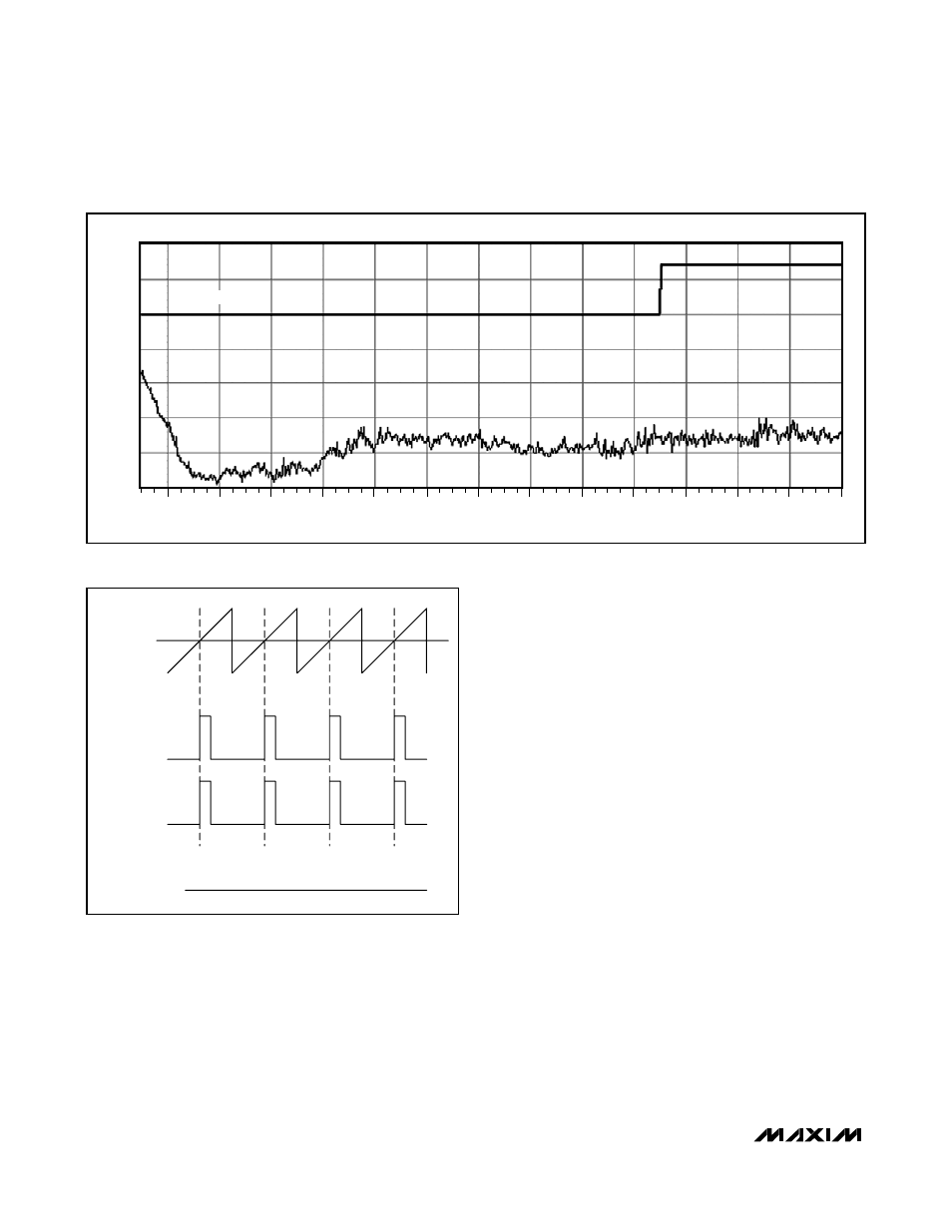
consumption, especially when idling. When no signal is
present at the input of the MAX9796, the outputs switch
as shown in Figure 4. Because the MAX9796 drives the
speaker differentially, the two outputs cancel each other,
resulting in no net idle mode voltage across the speaker,
minimizing power consumption.
DirectDrive
Traditional single-supply headphone amplifiers have
outputs biased at a nominal DC voltage (typically half
the supply) for maximum dynamic range. Large cou-
pling capacitors are needed to block this DC bias from
the headphone. Without these capacitors, a significant
amount of DC current flows to the headphone, resulting
in unnecessary power dissipation and possible dam-
age to both headphone and headphone amplifier.
Maxim’s patented DirectDrive architecture uses a
charge pump to create an internal negative supply volt-
age. This allows the headphone outputs of the
MAX9796 to be biased at GND, almost doubling
dynamic range while operating from a single supply.
With no DC component, there is no need for the large
DC-blocking capacitors. Instead of two large (220µF,
typ) tantalum capacitors, the MAX9796 charge pump
requires two small ceramic capacitors, conserving
board space, reducing cost, and improving the fre-
quency response of the headphone amplifier. See the
Output Power vs. Load Resistance and Charge-Pump
Capacitor Size graph in the
Typical Operating
Characteristics
for details of the possible capacitor
sizes. There is a low DC voltage on the driver outputs
FREQUENCY (MHz)
AMPLITUDE (dB
µ
V/m)
40
30
60
80
100
120
140
160
180
200
220
240
260
280
300
35
30
25
20
15
10
5
EN55022B LIMIT
Figure 3. EMI with 76mm of Speaker Cable
VIN = 0V
OUT-
OUT+
VOUT+ - VOUT- = 0V
Figure 4. Outputs with No Input Signal