Detailed description – Rainbow Electronics MAX9796 User Manual
Page 14
MAX9796
2.3W, High-Power Class D Audio Subsystem
with DirectDrive Headphone Amplifiers
14
______________________________________________________________________________________
Detailed Description
The MAX9796 ultra-low-EMI, filterless, Class D audio
power amplifier features several improvements to
switch-mode amplifier technology. The MAX9796 fea-
tures active emissions limiting circuitry to reduce EMI.
Zero dead-time technology maintains state-of-the-art
efficiency and THD+N performance by allowing the
output FETs to switch simultaneously without cross-
conduction. A unique filterless modulation scheme and
a spread-spectrum modulation create a compact, flexi-
ble, low-noise, efficient audio power amplifier while
occupying minimal board space. The differential input
architecture reduces common-mode noise pickup with
or without the use of input-coupling capacitors. The
MAX9796 can also be configured as a single-ended
input amplifier without performance degradation.
The MAX9796 features three fully differential input pairs
(INA_, INB_, INC_) that can be configured as stereo
single-ended or mono differential inputs. I
2
C provides
control for input configuration, volume level, and mixer
configuration. DirectDrive allows the headphone and
mono receiver amplifiers to output ground-referenced
signals from a single supply, eliminating the need for
large DC-blocking capacitors. Comprehensive click-
and-pop suppression minimizes audible transients dur-
ing the turn-on and turn-off of amplifiers.
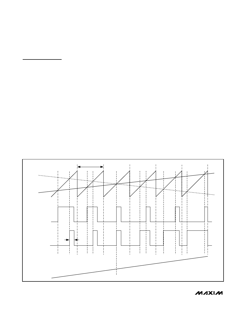
Class D Speaker Amplifier
Comparators monitor the audio inputs and compare the
complementary input voltages to a sawtooth waveform.
The comparators trip when the input magnitude of the
sawtooth exceeds their corresponding input voltage.
The active emissions limiting circuitry slightly reduces
the turn-on rate of the output H-bridge by slew-rate lim-
iting the comparator output pulse. Both comparators
reset at a fixed time after the rising edge of the second
comparator trip point, generating a minimum-width
pulse (t
ON(MIN)
, 100ns typ) at the output of the second
comparator (Figure 1). As the input voltage increases
or decreases, the duration of the pulse at one output
increases while the other output pulse duration remains
the same. This causes the net voltage across the
speaker (V
OUT+
- V
OUT-
) to change. The minimum-
width pulse helps the device to achieve high levels of
linearity.
OUT+
OUT-
V
IN-
V
IN+
V
OUT+
- V
OUT-
t
ON(MIN)
t
SW
Figure 1. Outputs with an Input Signal Applied