Rainbow Electronics MAX5295 User Manual
Page 25
MAX5290–MAX5295
Buffered, Fast-Settling, Dual, 12-/10-/8-Bit,
Voltage-Output DACs
______________________________________________________________________________________
25
User-Programmable Input/Output (UPIO)
Configuration
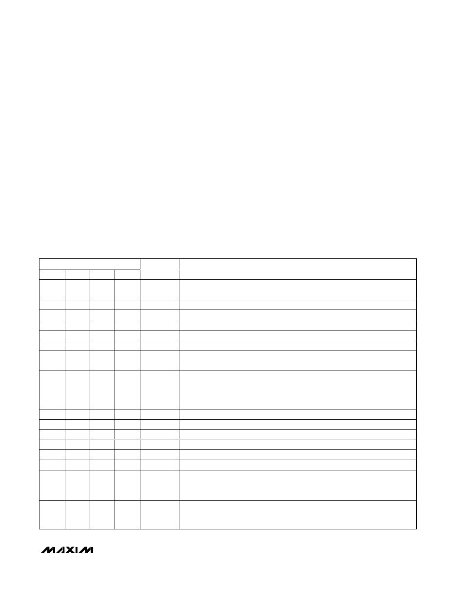
Table 22 lists the possible configurations for UPIO1 and
UPIO2. UPIO1 and UPIO2 use the selected function
when configured by the UP3–UP0 configuration bits.
LDAC
LDAC controls loading of the DAC registers. When
LDAC is high, the DAC registers are latched, and any
change in the input registers does not affect the con-
tents of the DAC registers or the DAC outputs. When
LDAC is low, the DAC registers are transparent, and the
values stored in the input registers are fed directly to the
DAC registers, and the DAC outputs are updated.
Drive LDAC low to asynchronously load the DAC regis-
ters from their corresponding input registers (DACs that
are in shutdown remain shut down). The LDAC function
does not require any activity on CS, SCLK, or DIN. If
LDAC is brought low coincident with a rising edge of
CS, (which executes a serial command modifying the
value of either DAC input register), then LDAC must
remain asserted for at least 120ns following the CS ris-
ing edge. This requirement applies only to serial com-
mands that modify the value of the DAC input registers.
See Figures 5 and 6 for timing details.
Table 22. UPIO Configuration Register Bits (UP3–UP0)
UPIO CONFIGURATION BITS
UP3
UP2
UP1
UP0
FUNCTION
DESCRIPTION
0
0
0
0
LDAC
Active-Low Load DAC Input. Drive low to asynchronously load all DAC registers
with data from input registers.
0
0
0
1
SET
Active-Low Input. Drive low to set all input and DAC registers to full scale.
0
0
1
0
MID
Active-Low Input. Drive low to set all input and DAC registers to midscale.
0
0
1
1
CLR
Active-Low Input. Drive low to set all input and DAC registers to zero scale.
0
1
0
0
PDL
Active-Low Power-Down Lockout Input. Drive low to disable software shutdown.
0
1
0
1
Reserved
This mode is reserved. Do not use.
0
1
1
0
SHDN1K
Active-Low 1k
Ω Shutdown Input. Overrides PD_1 and PD_0 settings. Drive
SHDN1K low to pull OUTA and OUTB to AGND with 1k
Ω.
0
1
1
1
SHDN100K
Active-Low 100k
Ω Shutdown Input. Overrides PD_1 and PD_0 settings. For the
MAX5290/MAX5292/MAX5294, drive SHDN100K low to pull OUTA and OUTB to
AGND with 100k
Ω. For the MAX5291/MAX5293/MAX5295, drive SHDN100K low to
leave OUTA and OUTB high impedance.
1
0
0
0
DOUTRB
Data Read-Back Output
1
0
0
1
DOUTDC0
Mode 0 Daisy-Chain Data Output. Data is clocked out on the falling edge of SCLK.
1
0
1
0
DOUTDC1
Mode 1 Daisy-Chain Data Output. Data is clocked out on the rising edge of SCLK.
1
0
1
1
GPI
General-Purpose Logic Input
1
1
0
0
GPOL
General-Purpose Logic-Low Output
1
1
0
1
GPOH
General-Purpose Logic-High Output
1
1
1
0
TOGG
Toggle Input. Toggles DAC outputs between data in input registers and data in
DAC registers. Drive low to set all DAC outputs to values stored in input registers.
Drive high to set all DAC outputs to values stored in DAC registers.
1
1
1
1
FAST
FAST/SLOW Settling-Time Mode Input. Drive low to select FAST mode (3µs) or
drive high to select SLOW settling mode (10µs). Overrides the SPDA and SPDB
settings.