Table 10. data format for write mode – Rainbow Electronics MAX9671 User Manual
Page 31
MAX9670/MAX9671
Low-Power Audio/Video Switch with Audio
Volume Control for Dual SCART Connectors
______________________________________________________________________________________
31
PIN (MAX9670)
NAME
TYPE
SIGNAL
LOAD
31
ENC_C_IN
Input
None
N/A
32
ENC_R/C_IN
Input
50% flat field
N/A
33
TV_R/C_OUT
Output
50% flat field
150
Ω to ground
34
VCR_R/C_OUT
Output
50% flat field
150
Ω to ground
35
VCR_Y/CVBS_OUT
Output
50% flat field
150
Ω to ground
36
TV_Y/CVBS_OUT
Output
50% flat field
150
Ω to ground
37
VCR_Y/CVBS_IN
Input
None
N/A
38
TV_Y/CVBS_IN
Input
None
N/A
39
ENC_Y_IN
Input
None
N/A
40
ENC_Y/CVBS_IN
Input
50% flat field
N/A
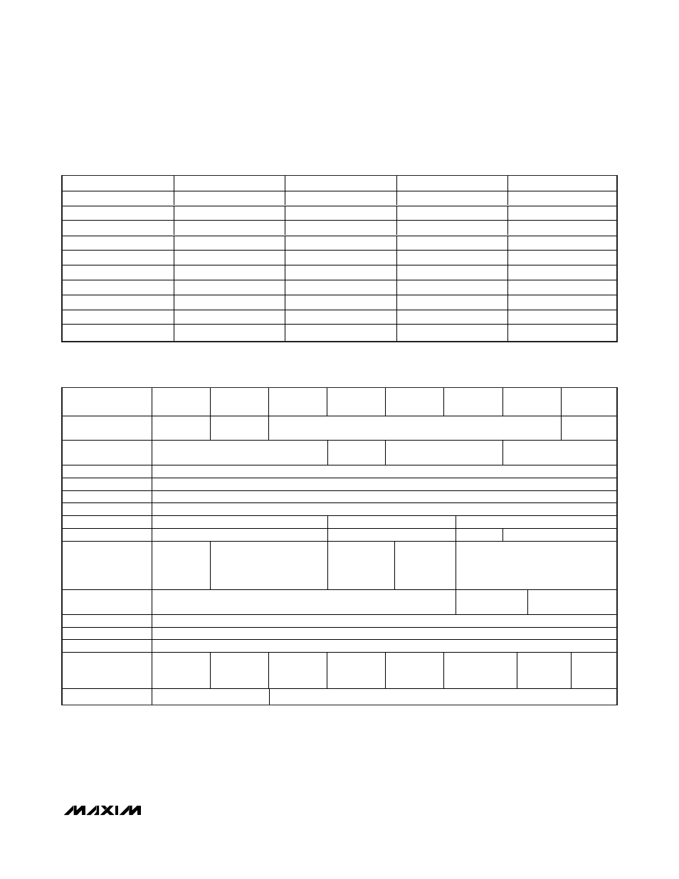
Table 9. Conditions for Average Power Consumption Measurement (continued)
REGISTER
ADDRESS (hex)
BIT 7
BIT 6
BIT 5
BIT 4
BIT 3
BIT 2
BIT 1
BIT 0
00h
Not used
TV ZCD
TV volume control
TV audio
output mute
01h
Not used
Interrupt
enable
VCR audio selection
TV audio selection
02h
Not used
03h
Not used
04h
Not used
05h
Not used
06h
Not used
TV G and B video switch
TV video switch
07h
Not used
Set TV fast switching
Not used
Set TV slow switching
08h
VCR_R/C_IN
clamp
Not used
ENC R/G/B
high-
impedance
bias
ENC_R/C_IN
clamp
VCR video switch
09h
Not used
VCR_R/C_OUT
ground
Set VCR slow
switching
0Ah
Not used
0Bh
Not used
0Ch
Not used
0Dh
VCR_Y/
CVBS_OUT
enable
VCR_R/
C_OUT
enable
TV_R/
C_OUT
enable
TV_G_OUT
enable
TV_B_OUT
enable
TV_Y/
CVBS_OUT
enable
TVOUT_FS
enable
Not used
10h
Operating mode
Not used
Table 10. Data Format for Write Mode