Rainbow Electronics MAX9671 User Manual
Page 14
MAX9670/MAX9671
Low-Power Audio/Video Switch with Audio
Volume Control for Dual SCART Connectors
14
______________________________________________________________________________________
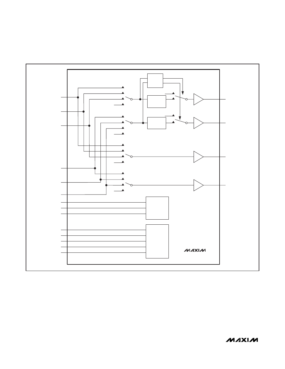
Audio Section
The MAX9670 audio circuit is essentially a stereo,
2-by-2, nonblocking, audio crosspoint with output dri-
vers. The encoder (stereo audio DAC) and the VCR are
the two input sources, and the two outputs go to the TV
SCART connector and the VCR SCART connector. See
Figure 1. The MAX9671 audio circuit is similar to that of
the MAX9670 except that it is a stereo, 3-by-2,
nonblocking audio crosspoint with TV as the third input
source.
The integrated charge pump inverts the +3.3V supply
to create a -3.3V supply. The audio circuit operates
from bipolar supplies so the audio signal is always
biased to ground.
ENC_INL
VCR_INL
x4
ZCD
(0.5V
RMS
FULL-SCALE INPUT)
(2V
RMS
FULL-SCALE OUTPUT)
(2V
RMS
FULL-SCALE OUTPUT)
TV_OUTL
TV_OUTR
MUTE
V
AUD
C1P
EP
C1N
CPVSS
CHARGE
PUMP
SCL
SDA
REGISTER
CONTROL
DEV_ADDR
MUTE
MUTE
MUTE
MUTE
VCR_OUTL
VCR_OUTR
*TV_INL
ENC_INR
VCR_INR
*TV_INR
x4
x4
VOLUME
CONTROL
0dB TO -62dB
VOLUME
CONTROL
0dB TO -62dB
*MAX9671 ONLY.
MUTE
MAX9670/MAX9671
x4
Figure 1. MAX9670/MAX9671 Audio Section Functional Diagram