Rainbow Electronics MAX9671 User Manual
Page 2
MAX9670/MAX9671
Low-Power Audio/Video Switch with Audio
Volume Control for Dual SCART Connectors
2
_______________________________________________________________________________________
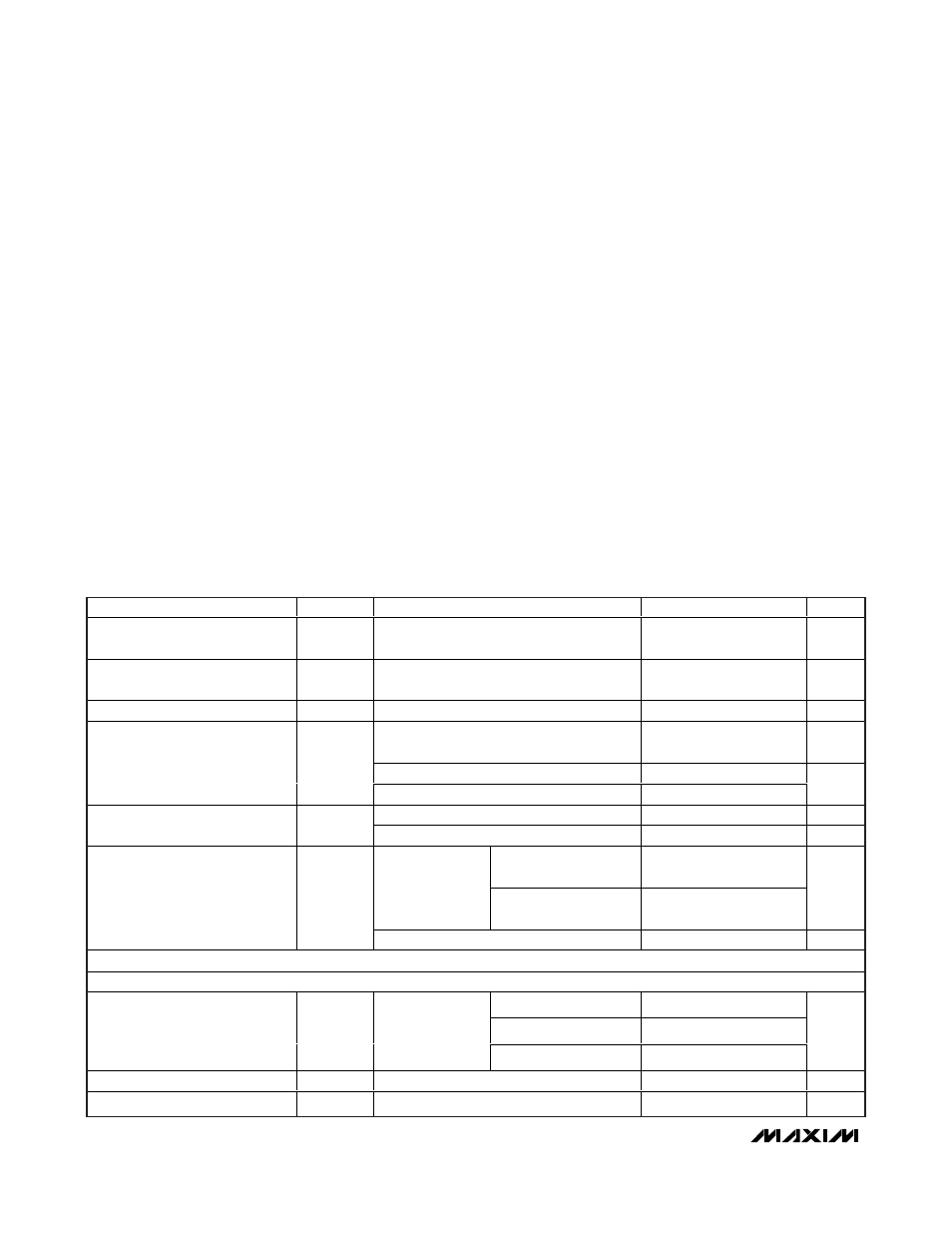
ABSOLUTE MAXIMUM RATINGS
ELECTRICAL CHARACTERISTICS
(V
12
= 12V, V
VID
= V
AUD
= 3.3V, V
GNDVID
= V
EP
= 0V, no load, T
A
= 0°C to +70°C, unless otherwise noted. Typical values are at
T
A
= +25°C.) (Note 1)
Stresses beyond those listed under “Absolute Maximum Ratings” may cause permanent damage to the device. These are stress ratings only, and functional
operation of the device at these or any other conditions beyond those indicated in the operational sections of the specifications is not implied. Exposure to
absolute maximum rating conditions for extended periods may affect device reliability.
V
VID
to GNDVID........................................................-0.3V to +4V
V
12
to EP.................................................................-0.3V to +14V
V
AUD
to EP ...............................................................-0.3V to +4V
EP to GNDVID .......................................................-0.1V to +0.1V
All Video Inputs, VCRIN_FS to GNDVID...................-0.3V to +4V
All Audio Inputs to EP .........................................-1V to (EP + 1V)
SDA, SCL, DEV_ADDR, INT to GNDVID ..................-0.3V to +4V
TV_SS, VCR_SS to EP .................................-0.3V to (V
12
+ 0.3V)
Current
All Video/Audio Inputs ...................................................±20mA
C1P, C1N, CPVSS .........................................................±50mA
Output Short-Circuit Current Duration
Video and Fast-Switching Outputs to V
VID
,
GNDVID.................................................................Continuous
Audio Outputs to V
AUD
, EP .....................................Continuous
TV_SS, VCR_SS to V
12
, EP......................................Continuous
Continuous Power Dissipation (T
A
= +70°C)
40-Pin TQFN-EP (derate 26.3mW/°C above +70°C) ...2105.3mW
44-Pin TQFN-EP (derate 26.3mW/°C above +70°C)...2222.2mW
Operating Temperature Range...............................0°C to +70°C
Junction Temperature ......................................................+150°C
Storage Temperature Range .............................-65°C to +150°C
Lead Temperature (soldering, 10s) .................................+300°C
PARAMETER
SYMBOL
CONDITIONS
MIN
TYP
MAX
UNITS
Video Supply Voltage Range
V
VID
Inferred from video PSRR test at 3V and
3.6V
3
3.3
3.6
V
Audio Supply Voltage Range
V
AUD
Inferred from audio PSRR test at 3V and
3.6V
3
3.3
3.6
V
V
12
Supply Voltage Range
V
12
Inferred from slow-switching levels
11.4
12
12.6
V
Normal operation; all video output
amplifiers are enabled and muted (Note 2)
16
30
mA
Standby mode, slow switch inputs low
1500
V
VID
Quiescent Supply Current
I
VID_Q
Shutdown
35
µA
Normal operation (Note 2)
3.2
6
mA
V
AUD
Quiescent Supply Current
I
AUD_Q
Shutdown
35
µA
Slow-switching output
set to low-level
0.3
100
Normal operation
(Note 2)
Slow-switching output
set to medium-level
475
µA
V
12
Quiescent Supply Current
I
12_Q
Shutdown, T
A
= +25°C
10
µA
VIDEO CHARACTERISTICS
DC-COUPLED INPUT
V
VID
= 3V
1.15
V
VID
= 3.135V
1.15
Input Voltage Range
V
IN
R
L
= 75
Ω to
GNDVID or 150
Ω
to V
VID
/2; inferred
from gain test
V
VID
= 3.3V
1.3
V
P-P
Input Current
I
IN
V
IN
= 0.3V, T
A
= +25°C
1
2
µA
Input Resistance
R
IN
300
k
Ω