Rc220x – Rainbow Electronics RC2200 User Manual
Page 13
RC220x
2005 Radiocrafts AS
RC220x Data Sheet (rev. 1.0)
Page 13 of 17
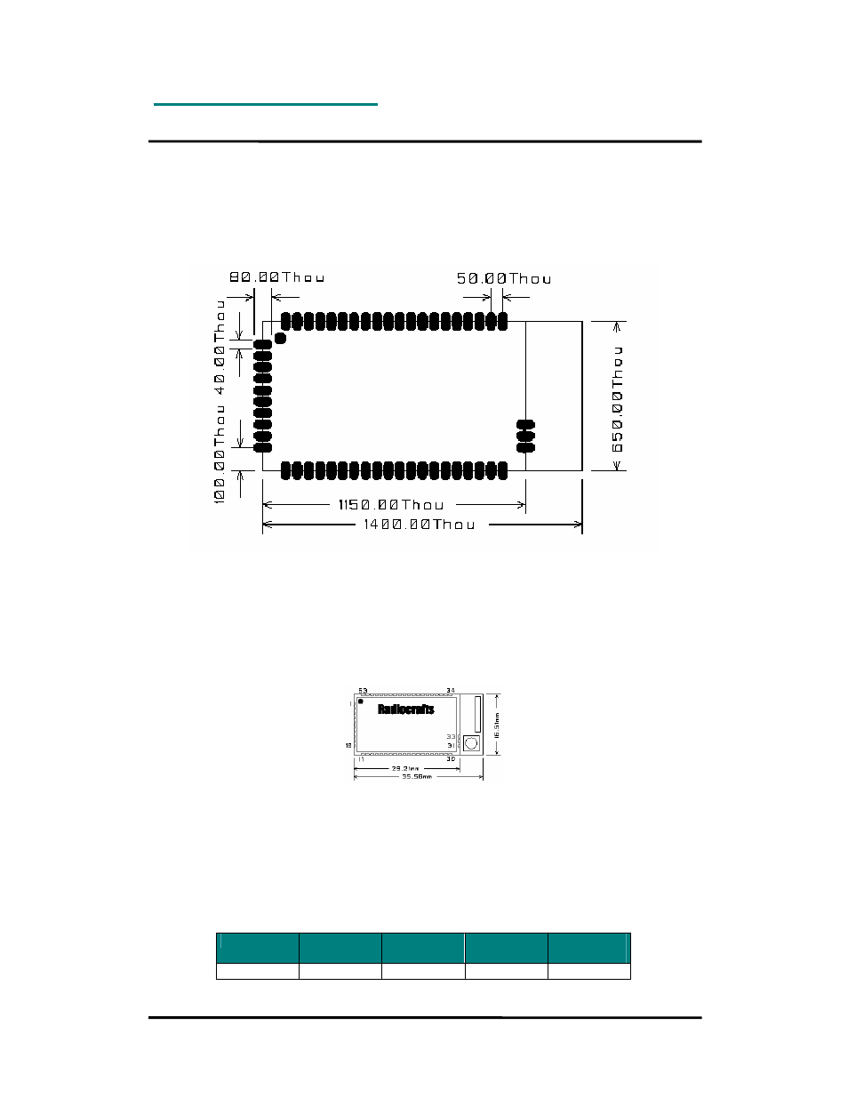
PCB Layout Recommendations
The recommended layout pads for the module are shown in the figure below (top view, pin 1
is in upper left corner, see pin assignment at page 4). All dimensions are in thousands of an
inch (mil). The circle in upper left corner is an orientation mark only, and should not be a part
of the copper pattern.
The area underneath the module should be covered with solder resist in order to prevent
short circuiting the test pads on the back side of the module. A solid ground plane is
preferred. Unconnected pins should be soldered to the pads, and the pads should be left
floating. For the module version with integrated antenna or MMCX connector, the RF pad (pin
31) can be soldered, but the pad should not be connected further. The two ground pads (pin
30 and 32 on the right side) should be grounded for all variants.
Mechanical Drawing
Mechanical Dimensions
The module size is 0.65” x 1.15” x 0.14” (16.5 x 29.2 x 3.5 mm) without the antenna / MMCX
connector. The length is 1.4” (35.6 mm) with the optional antenna / MMCX RF connector.
Carrier Tape and Reel Specification
Carrier tape and reel is in accordance with EIA Specification 481.
Tape width Component
pitch
Hole pitch
Reel
diameter
Units per
reel
56 mm
20 mm
4 mm
13”
Max 800