Frame - system -main -gpi, Installation – TC Electronic DB8 MKII User Manual
Page 34
34
frame - sysTem -maIn -GpI
Installation
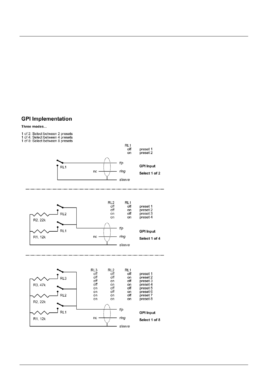
Selection between up to 8 presets is achieved by feeding the processor a DC voltage to the 1/4” jack input labeled “Pedal”.
The input voltage is compared against voltage windows that correspond to certain presets.
Between the valid voltage windows, invalid windows have been inserted to protect against erratic operation. The processor
constantly monitors the GPI input, and only if several consecutive measurements point to the same, valid voltage window,
a recall is performed.
The voltage windows chosen enable easy “binary relay encoding” as shown in fig. 1. If long cable runs are required, HF
decoupling using a ceramic capacitor across the Tip and Sleeve terminals inside the jack plug may be indicated.
Note: The ring terminal of the 1/4” jack is not used.
Fig 1, Relay coding of 2, 4 and 8 preset GPI configurations