Dsp & card connection – TC Electronic DB8 MKII User Manual
Page 12
12
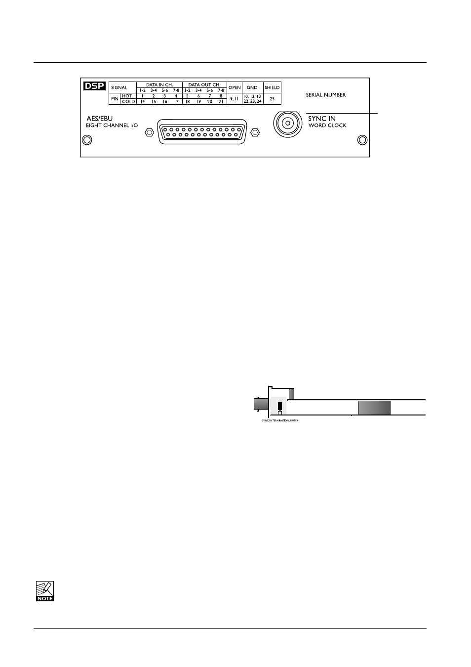
Dsp & CarD COnneCTIOn
Use the supplied cable to connect the AES/EBU Inputs/
Outputs.
Cable type is twisted pair (12 pairs) with common screen.
Recommended impedance: 110 Ohm.
One end is equipped with an AES/EBU 25 pin D-Sub
connector, the other end is equipped with four male XLR’s
and four female XLR’s.
Male XLR’s are marked with: Out - 1 to 4.
Female XLR’s are marked with: IN- 1 to 4.
Extension cables must be constructed according to AES/
EBU-3 standards.
Following is the pin-out:
Cable pair
Pin number
number
XLR
XLR-pin Assignment
1
1a
Female 1
2
Input 1/2 +
2
2a
Female 2
2
Input 3/4 +
3
3a
Female 3
2
Input 5/6 +
4
4a
Female 4
2
Input 7/8 +
5
5a
Male 1
2
Output 1/2 +
6
6a
Male 2
2
Output 3/4 +
7
7a
Male 3
2
Output 5/6 +
8
8a
Male 4
2
Output 7/8 +
9
No connection
No connection
10
9a
Female 1
1
Common
11
No connection
No connection
12
9b
Female 2
1
Common
13
10a
Female 3
1
Common
13
10b
Female 4
1
Common
14
1b
Female 1
3
Input 1/2 -
15
2b
Female 2
3
Input 3/4 -
16
3b
Female 3
3
Input 5/6 -
17
4b
Female 4
3
Input 7/8 -
18
5b
Male 1
3
Output 1/2 -
19
6b
Male 2
3
Output 3/4 -
20
7b
Male 3
3
Output 5/6 -
21
8b
Male 4
3
Output 7/8 -
22
11a
Male 1
1
Common
23
11b
Male 2
1
Common
24
12a
Male 3
1
Common
24
12b
Male 4
1
Common
25
Shield
no connection
Common
Twisted cable pairs must be respected
Sync In Word Clock
For connections to external clock via the standard BNC
connector (see illustration above).
When several devices are connected in a chain and
synced via Word Clock, termination on the last device of
the chain is necessary.
As the DB8/DB4 is expected to be the last unit in such a
chain (or the only), the factory default setting on the DSP
card is: TERMINATED (75 Om).
If you need to terminate the Word Clock signal elsewhere
in the chain you will need to un-terminate the DSP card.
To do this you must remove the DSP card from the
mainframe and remove the termination jumper:
• Switch off the power and disconnect main power cord.
• Loosen the two screws holding the DSP card and
remove the card gently.
• Remove the terminating jumper near the BNC plug.
• Insert the card gently in the DSP slot and remount
the screws.
Pins connected via jumper
: Terminated (75 Om).
Pins NOT connected via jumper : Not Terminated
Termination jumper
BNC
connector