Installing a rear module – Cobalt Digital FUSION 3G 9921-FS 3G_HD_SD Frame Sync User Manual
Page 46
2
Installing a Rear Module
2-10
9921-FS PRODUCT MANUAL
9921-FS-OM (V1.15)
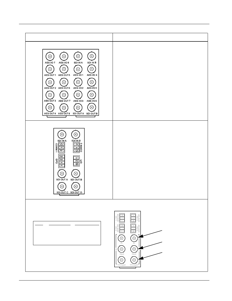
RM20-9921-G Base Rear Module
Provides the following connections:
• Two 3G/HD/SD-SDI video input BNC (
SDI IN A and
SDI IN B
)
• Eight AES I/O BNC (AES-3id) input/outputs
(
AES I/O 1
thru
AES I/O 8
; I/O function of each
connection is software-configurable)
• Eight additional AES BNC (AES-3id) outputs
(
AES OUT 1
thru
AES OUT 8)
• Two 3G/HD/SD-SDI video output BNCs
(
SDI OUT A and SDI OUT B
)
Note: Operational only in conjunction with card option
+AESOUT16. Rear module mates with base
Fusion3G
®
card and option expansion card.
RM20-9921-H Base Rear Module
Provides the following connections:
• Two 3G/HD/SD-SDI video input BNCs (
SDI IN A
and SDI IN B
)
• Two opto-isolated GPI inputs (terminals GPI 1-G
and GPI 2-G)
• Two SPST NO GPO relay closure contacts
(floating) (terminals 1/1 and 2/2)
• Two RS485 serial ports; GUI configurable for
function (COMM1 and COMM2)
• Four 3G/HD/SD-SDI video output BNCs
(
SDI OUT A thru SDI OUT D
)
Note: When using Y/C (“S-video”) analog input or output, connections are as shown below and not as shown on label
(which correspond to YPbPr and composite mode connections).
Table 2-1
9921-FS Rear Modules — continued
9921-FS Rear Module
Description
Label
Y/C Input Mode
Y/C Output Mode
Pr
C
C
Pb/C
Y
Y
Y/Cmpst
NC
Composite
C
Y
See table