Turbosmart BOOST CONTROLLERS – ELECTRONIC - e-Boost STREET 30psi Manual User Manual
Page 5
5
RPM DISPLAY CONFIGURATION (CYL)
If you have connected the yellow RPM wire to an RPM signal from your ECU or negative terminal of an ignition coil you will need to
input the number of cylinders / rotors in order to configure the RPM signal correctly i.e. the number of pulses per revolution being picked
up from the RPM output of the ECU. The number of cylinders available is between 1 and 16. The RPM input can accept a square wave
signal between 3.5 and 12V. For Mazda Rotary engines, 13B and 20B engines can be configured as 4 and 6 cylinders respectively.
LIGHT DIM (DM)
The brightness of the display can be adjusted on a scale of 0 – 6. The display can also be dimmed automatically by earthing the green
wire when the vehicle’s light system is switched on and setting the scale to 0. This function cannot be used when switch logic is set to
ESP.
SWITCH LOGIC (SL)
The switch logic determines how the E-Boost Street switches between boost groups BG1 and BG2. It is factory set to internal switching
(ISP) where boost groups are changed by pushing the knob. Alternatively, boost groups can be switched remotely when the switch logic
is set to external switching (ESP). By earthing the green wire using a switch, you can toggle change from SP1 to SP2. Un-earthing this
wire will return the set point back to SP1. This function cannot be used with the dimming function.
BOOST CORRECTION (COR)
This function is use to reduce or eliminate boost drop off at high RPM. Switching this function on will display the boost correction menu
in the boost group menu. This function is best performed on a chassis dyno where the graph of the boost curve can be displayed and
accurately interpreted.
The boost correction function requires 3 parameters to work; the START RPM, the END RPM and the correction factor.
START RPM (RP1): This is the engine RPM at which boost begins to drop off.
END RPM (RP2): This is the engine RPM at which you want to turn off the boost correction function, normally set at redline.
Correction factor (FAC): The percentage at which boost is dropping off between the START and END RPM.
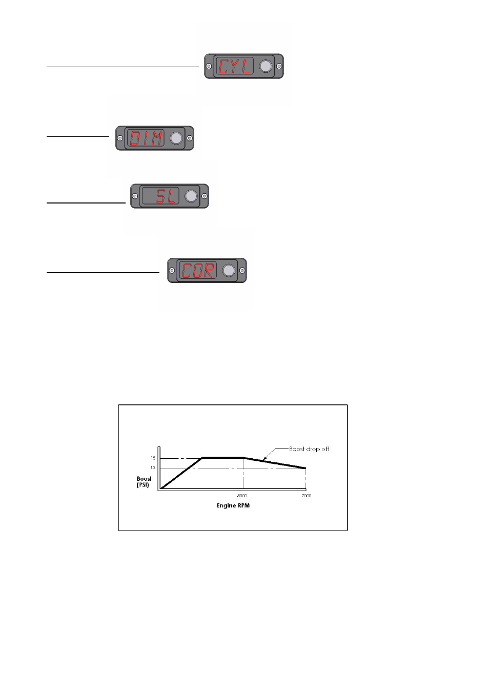
Example:
The following boost curve shows that between 5000 and 7000 RPM, the boost drops off from 15 PSI to 10 PSI.
Boost curve before COR is setup