Turbosmart WASTEGATES – EXTERNAL - Ultra-Gate 38 (no locking ring) User Manual
Page 4
www.TURBOSMARTONLINE.com
4
WARNING! Fitting a heavier wastegate spring may cause a higher than expected increase in boost pressure.
Turbosmart recommends adjusting your boost controller back to its minimum setting and measuring the new minimum boost pressure
achieved by the new spring, before increasing your boost pressure again.
1)
Remove the wastegate from the exhaust manifold. Use CAUTION! The wastegate may still be HOT!
2)
Hold the cap down in a press or vice. Using a 5mm Allen Key, remove the M6 Socket head cap screws that secure the upper
wastegate cap. WARNING! The cap is under spring tension, wear safety glasses and remove with care! Slowly back off the
vice or press and remove the cap.
3)
Select and locate the required wastegate spring or combination of inner and outer springs on the upper diaphragm spring
support. See spring information above for detail on wastegate spring identification and selection.
4)
Ensure that the diaphragm is inside the diaphragm groove. The six holes on the outer ring of the wastegate diaphragm should
be in line with the 6 holes in the lower wastegate cap.
5)
Slowly push the top cap down on the lower diaphragm housing in a vice or press. As the cap reaches the diaphragm, slowly
turn the cap left and right as you lower the cap to the lower diaphragm housing. Make sure that the convolution of the
diaphragm is not pinched between the top cap and the lower diaphragm housing. Refit the upper wastegate cap re-using the
M6 Socket head cap screws. Again you may find it helpful to use a press to hold down the cap with a press or a clamp while
tightening these screws. Tighten the M6 Socket head cap screws using a 5mm Allen Key and torque to 8 N-m (5.9 lb-ft)
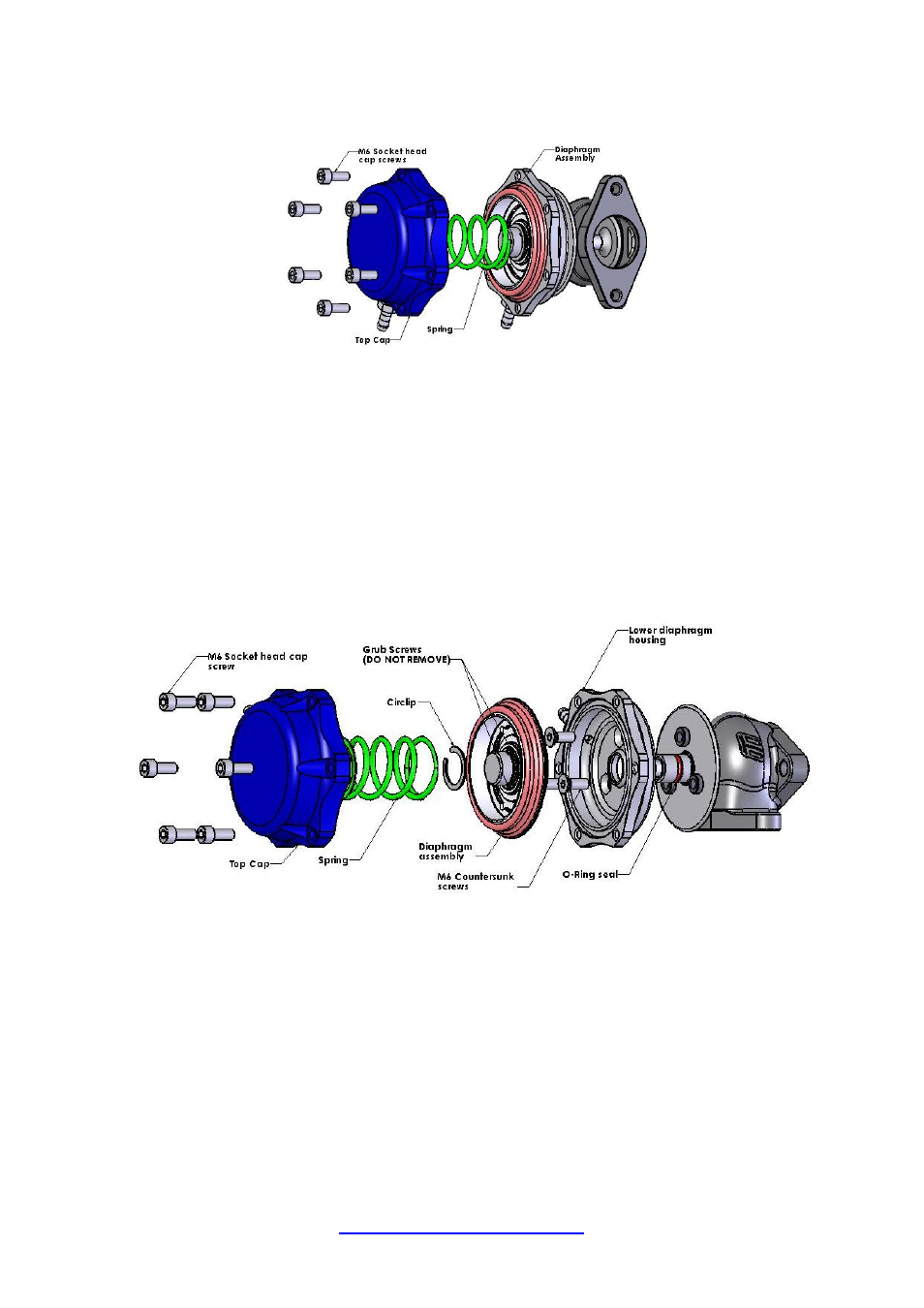
Diaphragm removal and lower diaphragm housing rotation
1)
Follow steps 1 and 2 of the spring change instructions.
2)
Using a pair of circlip pliers, remove the retaining circlip on the diaphragm support.
3)
Carefully back off the 3 securing grub screws in the top of the diaphragm support, DO NOT REMOVE COMPLETELY FROM
DIAPHAGM SUPPORT.
4)
Remove diaphragm assembly and valve.
5)
Remove the 3 M6 counter sunk cap screws and remove lower diaphragm housing. Check that the sealing O-Ring is in good
condition. Replace if necessary (TS-0501-3004).
6)
Refit the lower diaphragm housing in the desire orientation and replace M6 Countersunk screws.
7)
Slide the valve back through the guide and place the diaphragm assembly on top of the valve. Apply a small drop of Loctite
onto the threads of the grub screw and tighten. Make sure that the valve is hard up against the diaphragm assembly.
8)
Select and locate the required wastegate spring or combination of inner and outer springs on the upper diaphragm spring
support. See spring information above for detail on wastegate spring identification and selection.
9)
Ensure that the diaphragm is inside the diaphragm groove. The six holes on the outer ring of the wastegate diaphragm should
be in line with the 6 holes in the lower wastegate cap.