Electronics MC User Manual
Page 7
H:\MANUALS\IM0049C.DOC Installation Manual Model MC Shot Flow Controller
7 of 12
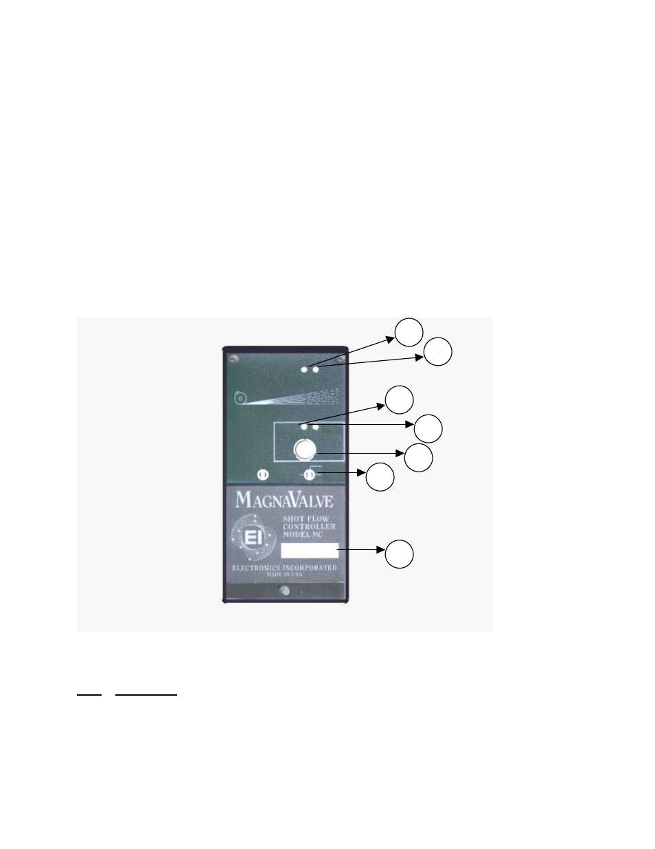
4. REMOTE - This LED indicator shows that the control is in the "Remote Mode" and a remote
analog 0-10 Vdc command is expected at screw terminal #10.
5. SETPOINT KNOB - This knob will set the desired shot flow rate when the control is in the
"Local Mode".
6. MODE SWITCH - This switch determines the controller mode of operation.
Right = Forced On
Middle = Forced Off
Left = Ready (waiting for "Enable" signal from machine at terminal #3)
7. DECAL - Space is provided for the customer to make additional notations.
FIGURE 1. FRONT PANEL - Operator Controls
7
6
5
4
3
2
1
FIGURE 2. FRONT PANEL - Technician Adjustments
Item Description
1.
SETPOINT LOCAL/REMOTE - This switch will select whether the setpoint
command comes from the front panel knob or from an external remote analog 0-10 Vdc
command.