Electronics MC User Manual
Page 10
H:\MANUALS\IM0049C.DOC Installation Manual Model MC Shot Flow Controller
10 of 12
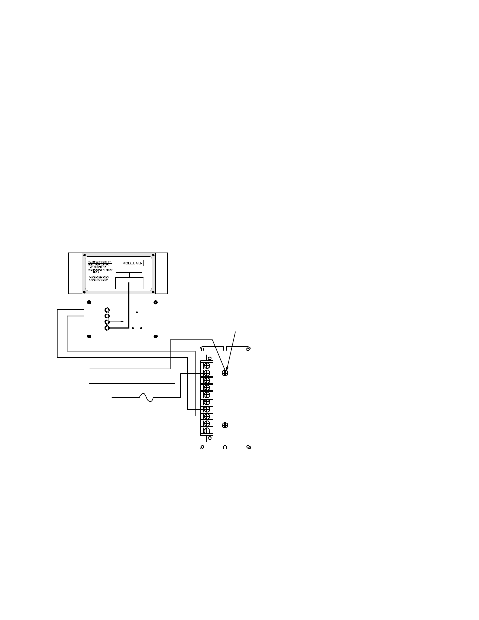
FIGURE 5. WIRING CONNECTIONS
1. Power Neutral (120 Vac)
2. Power Hot (120 Vac)
3. Enable Input (120 Vac)
4. (+) 10 Vdc Reference Output
5. (+) 12 Vdc Excitation Output
6. (-) 12 Vdc Excitation Output
7. (+) MagnaValve Output
8. (-) MagnaValve Output
9. Common - Shield
10. Remote Set Point Input (0-10 Vdc)
Green screw on back panel is for earth - chassis grounding.
1
2
3
4
5
6
7
8
9
10
MC CONTROLLER BACK VIEW
AC HOT
(120VAC)
NEUTRAL
GROUND GREEN
WHITE
BLACK
CABLE TO MAGNAVALVE:
16 AWG WIRE IN
CONDUIT OR SEAL-TITE
EARTH
GROUND
(SHIELD)
1 AMP
FUSE
END VIEW (with Valve Driver removed)
BACK OF VALVE DRIVER ( VD12 )
Red
Black
Orange
Brown
TABLE 6. SPECIFICATIONS
Power:
120 Vac, 50/60 Hertz, 50VA
Inputs:
Remote Command Set Point (0-10 Vdc)
Enable (92 - 120 Vac)
Outputs:
Valve Power 50 Vdc PWM at 10 Hertz