Powerboard, Installation instructions, Install lights – Rough Country 75141-15 User Manual
Page 5: Install running boards, Reinstall fuse, Install motor, Test doors and powerboards
PowerBoard
®
– Installation Instructions
Rev. L 0713
75141 pg. 5
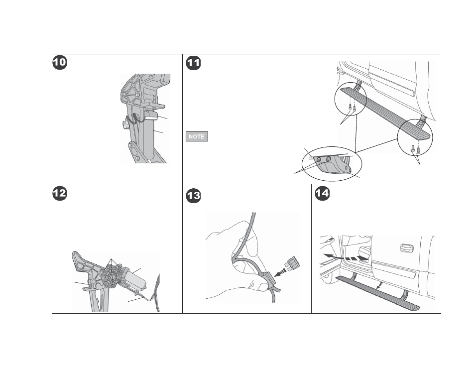
Clean the outboard surface
of the of the Linkage below
the bottom mounting bolt.
Peal the adhesive liner off
the back of the Light and
fi rmly press it 1/8" below
the mounting bolt. Plug the
light into the connector with
the black and orange wires
in the wire harness. Repeat
with the other three lights.
Secure lose wires with
Cable Ties.
Install Lights
Light
Linkage
Install Running Boards
M6-1.0 x 20mm
Socket Head Bolts
Linkage
PowerBoard
M6-1.0 x 20mm
Socket Head Bolts
M6-1.0 x 20mm
Socket Head Bolts
Reinstall the fuse in the harness.
Reinstall Fuse
Slide Motor assembly onto drive shaft and mounting
bosses of Motor Linkage assembly. Use three (3)
M6-1.0 x 35mm Socket Cap Screws and M6 Flat
Washers to secure Motor. Plug female connector
into Motor. Wrap any exposed wires from the motor
with electrical tape. Torque the screws to 5–7 ft. lbs.
(6.78–9.49 Nm or 60-84 in. lbs.).
Install Motor
Motor
Linkage
Motor
Wire
Harness
Open the doors to make sure that the PowerBoard
®
drops into position on each side of the vehicle.
Cycle boards several times and then fully tighten
all bolts.
Test Doors and PowerBoards
®
Mount the Steps to the linkages. Slide the mounting T-Nut
into position. Install M6-1.0 x 20mm Socket Head Bolts to
secure the boards. Use a 5mm Allen Wrench to tighten the
bolts.
Make sure the board moves up and down freely by hand.
If it binds, loosen the linkage to body attachment bolts and
adjust the linkage position until the boards move freely. Do
not tighten the bolts at this time.
Tightening the
fasteners before
cycling the step several times
may create a bind, causing a
squeaking sound and preventing
the boards from retracting
completely and evenly.
M6-1.0 x 35mm Socket Cap
Screws and M6 Flat Washers