Rough Country 692.20 User Manual
Page 3
Front Installation
1. The tools needed for this installation are on the back cover. A list of all parts are in the kit content sectio-
non the last page. Make sure you have all of the proper tools and understand these directions.
2. Chock the rear wheels and using a floor jack raise up the front of the Liberty and support the unibody
frame rails with jack stands. NEVER WORK UNDER AN UNSUPPORTED VEHICLE.
3. Starting on the passenger side of the Liberty remove the tire.
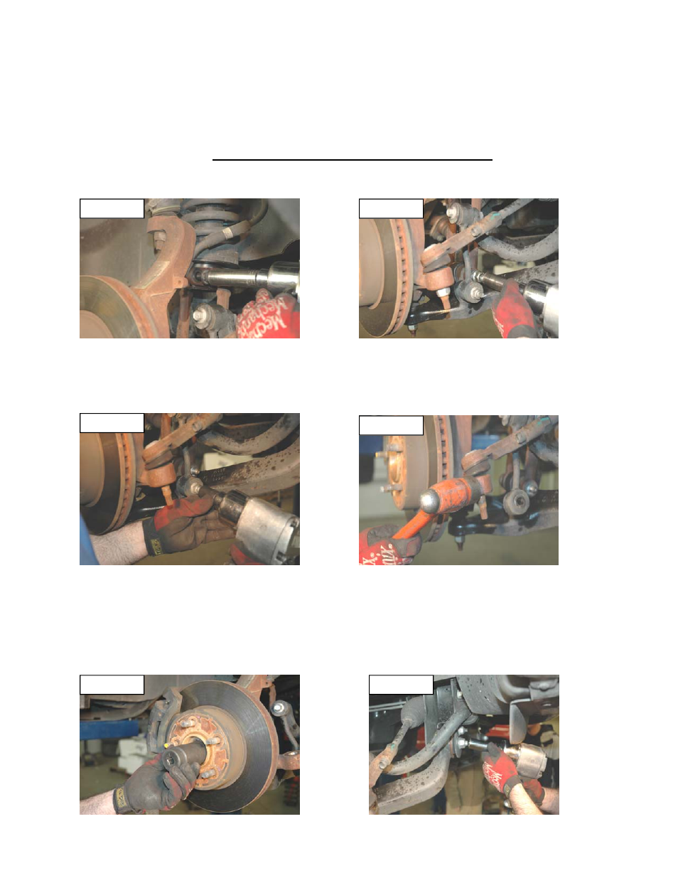
4. Using a 21mm deep-well socket remove the upper and lower strut fork nuts. See Figure 1 & 2.
5. Using a 18mm socket remove lower nuts from the sway bar links as shown in Figure 3. Then remove the
sway bar bolts and sway bar links. Retain for reuse.
6. Using a 19mm deep-well socket remove the tie-rod nut. Using a hammer hit the spindle as shown in Fig-
ure 4 until the tie-rod pops out. Never hit the tie-rod or the threaded shaft.
7. If you are working on a 4wd Liberty use a 36mm socket and remove the CV axle nut from the spindle. For
2wd this step will be skipped. See Figure 5. This is done to prevent any damage to the axle shaft from
over extension while installing the lift spacer.
8. Mark the lower control arm alignment cams and the lower arm. Loosen the Lower Control Arm Cam bolts
as shown in Figure 6 and adjust them so the bolts are towards the outside of the Liberty. Do not remove
these bolts.
Figure 1
Figure 2
Figure 4
Figure 3
Figure 5
Figure 6