Powerboard, Installation instructions, Disconnect fuse box – Rough Country 75138-15 User Manual
Page 8: Wiring, Route trigger wires
PowerBoard
®
– Installation Instructions
Rev. Q 0713
75138 / 75143 pg. 8
Disconnect Fuse Box
Locate the vehicle’s
Door Ajar wires on the
connector from Step 29.
Wiring
Door Ajar
Wires
Color Function
Violet
Driver Door Ajar Switch
Sensor
Violet / White
Passenger Door Ajar Switch
Sensor
Violet / Gray
Driver Rear Door Ajar
Switch Sensor
Violet / Yellow
Passenger Rear Door Ajar
Switch Sensor
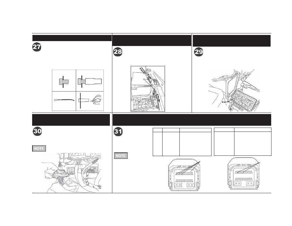
Route the purple Wire Harness trigger wires down
to the fuse box in front of the battery.
Use a 13mm wrench to remove the fuse box lid and
power lead. Depress the release tabs and lift the
fuse box to access the bottom.
Route Trigger Wires
Route Trigger Wires
Purple
Trigger
Wire
2009 – 2012 RAM 1500
2010 – Current RAM 2500/3500
2009 – 2012 RAM 1500
2010 – Current RAM 2500/3500
2009 – 2012 RAM 1500
2010 – Current RAM 2500/3500
2009 – 2012 RAM 1500
2010 – Current RAM 2500/3500
Locate the black connector with the gray latch, labeled
“G” on the bottom of the fuse box. Disconnect it.
Cavity Color
Function
11
Violet
Driver Door Ajar Switch
Sensor
12
Violet / White Passenger Door Ajar
Switch Sensor
16
Violet / Gray
Driver Rear Door Ajar
Switch Sensor
14
Violet / Yellow Passenger Rear Door Ajar
Switch Sensor
Door Ajar
Wires
Model Year
2011 – Current
Model Year
2009 – 2010
If you do not
have this
connector on the bottom
of the fuse box follow
steps 23-27.
If you do not have this connector on the
bottom of the fuse box follow steps 23-27.
Posi-Tap™
Instructions
Insert
Tighten
Strip 3/8"
Insert and
Tighten
The trigger wires are color coded to match the Door
Ajar wires. Use the Posi-Taps™ to splice the trigger
wires into the matching Door Ajar wires.
Proceed to Step 32.
Splice Trigger Wires into
Door Ajar Wires
2013 - Current RAM 1500