Powerboard, Installation instructions, Orient linkages – Rough Country 75138-15 User Manual
Page 5: Install linkages, Install front support bracket
PowerBoard
®
– Installation Instructions
Rev. Q 0713
75138 / 75143 pg. 5
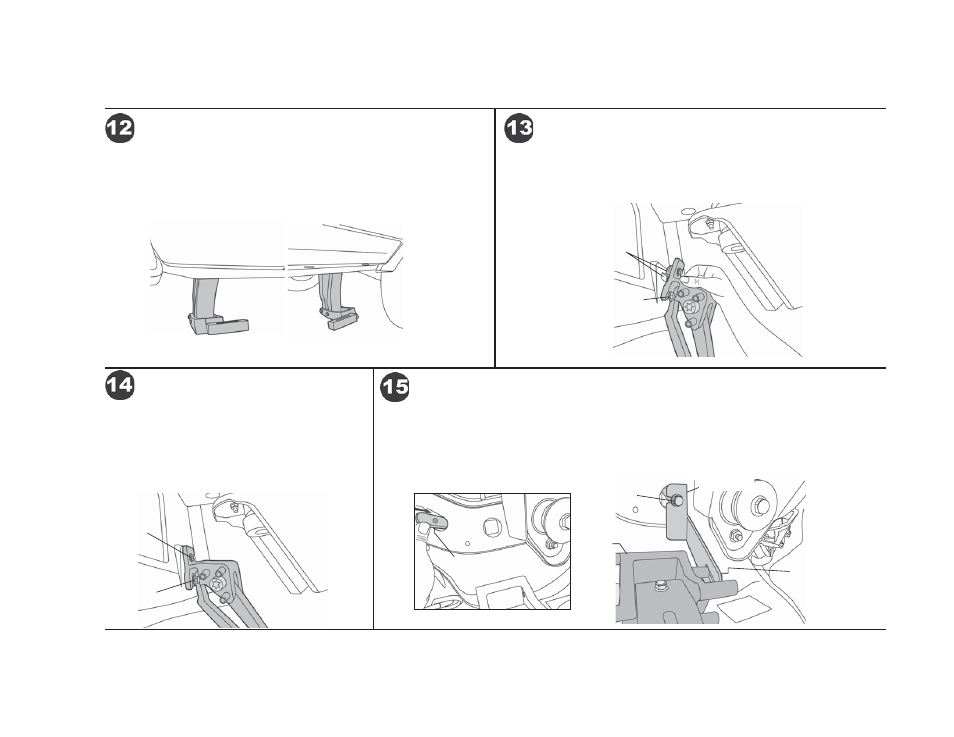
Orient the Linkages on the vehicle with the Idler Linkages to the rear and the
Motor Linkages to the front. The feet on the Linkages should face each other
on each side of the vehicle.
Orient Linkages
Retract the Linkage part way and make sure the Mounting Insert is in the
proper position. Tilt the Linkage and slide the mounting slots over the bolts
installed in Step 7. Rotate the Linkage until the Mounting Insert slips into the
slot in the sheet metal.
Install Linkages
M8-1.25 x 30
Hex Bolt
Slip
Mounting
Insert into
slot
Use a 10mm wrench to tighten the M6 Flange Hex Bolt
to 12 ft. lbs. Do not allow the bolt to rotate counter-
clockwise which may disengage the Mounting Insert.
Then tighten the lower Hex Bolts to 16 ft. lbs.
Repeat for all Linkages
Install Linkages
Tighten to
12 ft. lbs.
Tighten to
16 ft. lbs.
Driver’s Side Shown
Driver’s Side
Front Shown
Driver’s Side
Front Shown
Slide a Bracket Insert into the access hole in the body support member above the front Motor Link.
Push it forward and over to the hole next to the body mount. Thread an M8-1.25 x 30 Hex Bolt with
a Large Washer into the insert. Hook the Front Support Bracket over the Large Washer and attach
it to the top front boss on the Motor Linkage with an M6-1.0 x 15mm Socket Screw and M6 Flat
Washer. The M6 screw will go in the outboard slot on the left side and the inboard slot on the right.
Tighten all fasteners and repeat on other side.
Install Front Support Bracket
Driver’s Side Shown
Bracket
Insert
Front Support
Bracket
M8-1.25 x 30
Hex Bolt with
Large Washer
Motor
Linkage
M6-1.0 x 15mm
Socket Screw and M6
Flat Washer