Rough Country 170P User Manual
Page 3
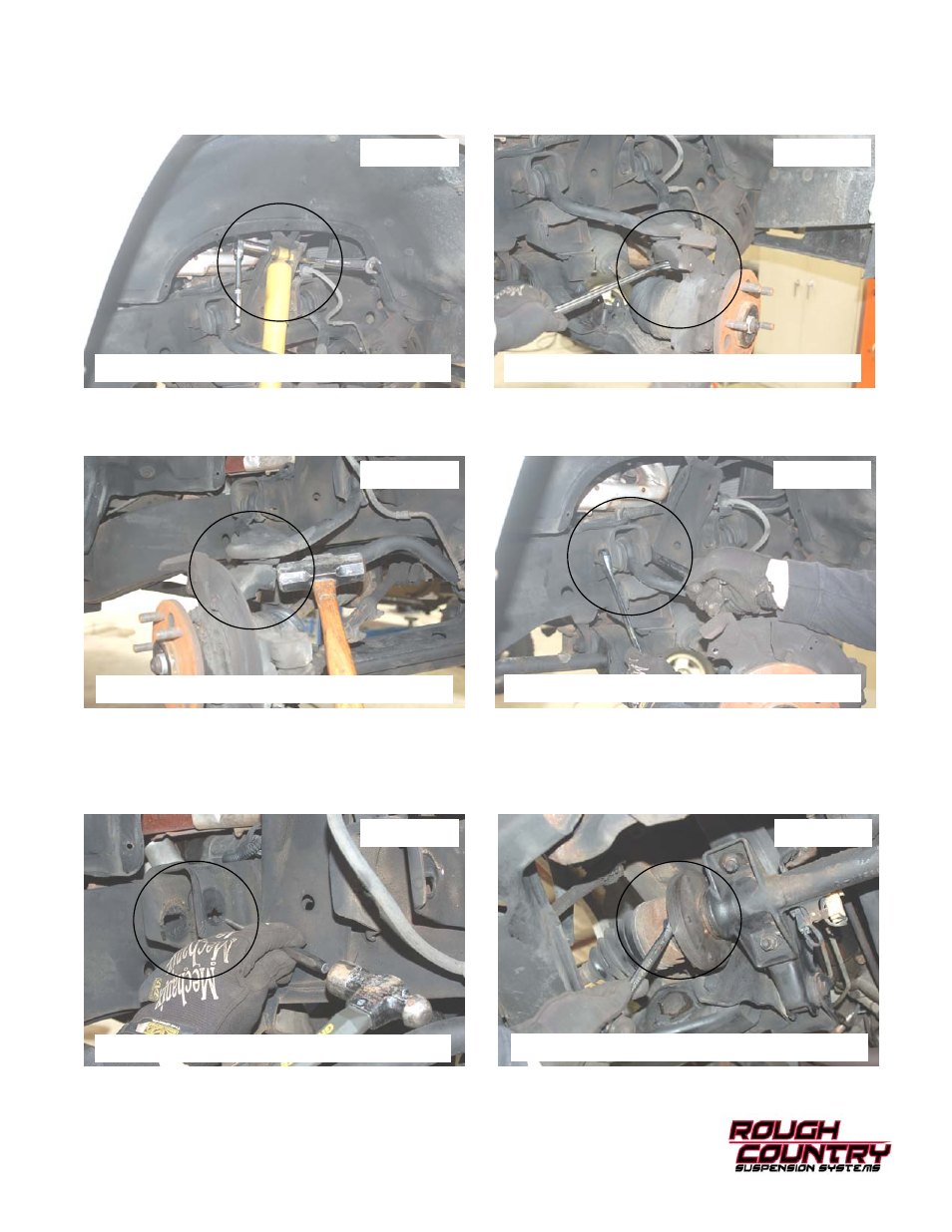
11. Remove the stock shock from the upper mount (Shown in Photo 7) and the lower mount using a 18mm socket /
wrench. Retain the stock hardware.
12. Remove the upper ball joint cotter pin and loosen the nut using a 1 1/16” wrench. See Photo 8. Retain the stock
hardware. Unplug the ABS sensor wire is equipped.
13. Support the lower control arm.
14. Strike the knuckle as shown to dislodge the upper ball joint. See Photo 9.
15. Remove the upper control arm hardware using a 21mm wrench / socket. See Photo 10.
16. On Pre 94 models the upper control arm alignment tabs may need to be removed. If applicable remove the perfo-
rated area as shown. See Photo 11.
17. Remove the factory lower skid plate using a 15mm wrench if equipped.
18. Remove the 12 bolts-6 per side that secure the half shafts to the differential using a 15mm wrench. Retain the fac-
tory hardware. See Photo 12.
PHOTO 7
PHOTO 8
PHOTO 9
PHOTO 10
PHOTO 11
PHOTO 12
REMOVE THE SHOCK ABSORBER
LOOSEN THE BALL JOINT HARDWARE
DISLODGE THE UPPER BALL JOINT
REMOVE THE UPPER ARM HARDWARE
REMOVE THE TABS IF NEEDED
REMOVE THE CV SHAFT BOLTS