Rough Country PERF662X User Manual
Page 7
1. Chock the front wheels. Jack up the rear of the vehicle and remove the tires and wheels. Place jack stands on
the frame rail to support the vehicle. Place a floor jack under the differential. Remove the stock shock absorbers
using a 15mm socket & 18mm wrench. Remove the sway bar links using a 15mm socket & wrench. Retain the
factory shock hardware.
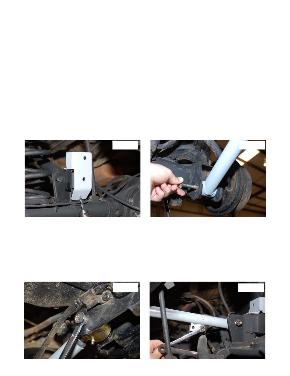
2. Disconnect the track bar from the axle bracket on driver side of vehicle using a T55 Torx bit and install the new
track bar relocation bracket in the stock location. See Photo 1. Secure to the stock location using the factory
hardware.
3. Remove the stock brake line from the driver side frame mount and axle mount. Install the new line using stock
hardware on the frame and axle.
4. Carefully lower the axle with the floor jack and remove the coil springs. NOTE: It may be necessary to use a coil
spring compressor to remove the stock coil springs. Be careful not to overextend the vent tube on the axle. It
may be necessary to disconnect the hose during installation and reroute the hose after installation.
5. Enlarge the holes in the factory mount to accommodate the two 5/16” bolt, using the bracket holes as a guide.
Install the 5/16” bolts, washers, nuts. Tighten using a 13 wrench. Do not install the track rod in the new bracket at
this time.
5. Remove and replace one suspension arm at a time.
6. Remove the lower arm from the axle and frame mount using a 21mm wrench & socket. Retain hardware.
7. Lubricate control arm bushings with a lithium grease or equivalent and install in the Rough Country control arm.
Adjust to 3/8” longer than the stock arm for a pre-alignment starting point. Tighten the jam nut using a 1 1/8”
wrench and install on the vehicle with the offset to the bottom using factory hardware as shown in Photo 2.
8. Repeat steps on the other side.
9. Remove the rear upper stock control arms from both the frame and axle mounts using a 15mm socket & wrench.
Retain the stock hardware for reuse. Remove the emergency brake line bracket from the stock control arm using
a 1/2” socket. Retain hardware for reuse.
10. Lubricate bushings with a lithium grease or equivalent and install the bushings and sleeves in the upper rear con-
trol arms.
11. Adjust the control arm to a length of 3/4” longer than stock arms (1/4” if using stock drive shaft) for a pre-
alignment starting point. Install the adjustable arms in the stock location and reuse factory hardware to install. Do
not tighten at this time. See Photo 3.
12. Reinstall the emergency brake bracket onto tab on upper control arm using a 1/2” wrench. Reuse factory hard-
ware and tighten. See Photo 4.
REAR INSTALLATION
PHOTO 1
PHOTO 2
PHOTO 3
PHOTO 4