Rough Country 280N2 User Manual
Page 8
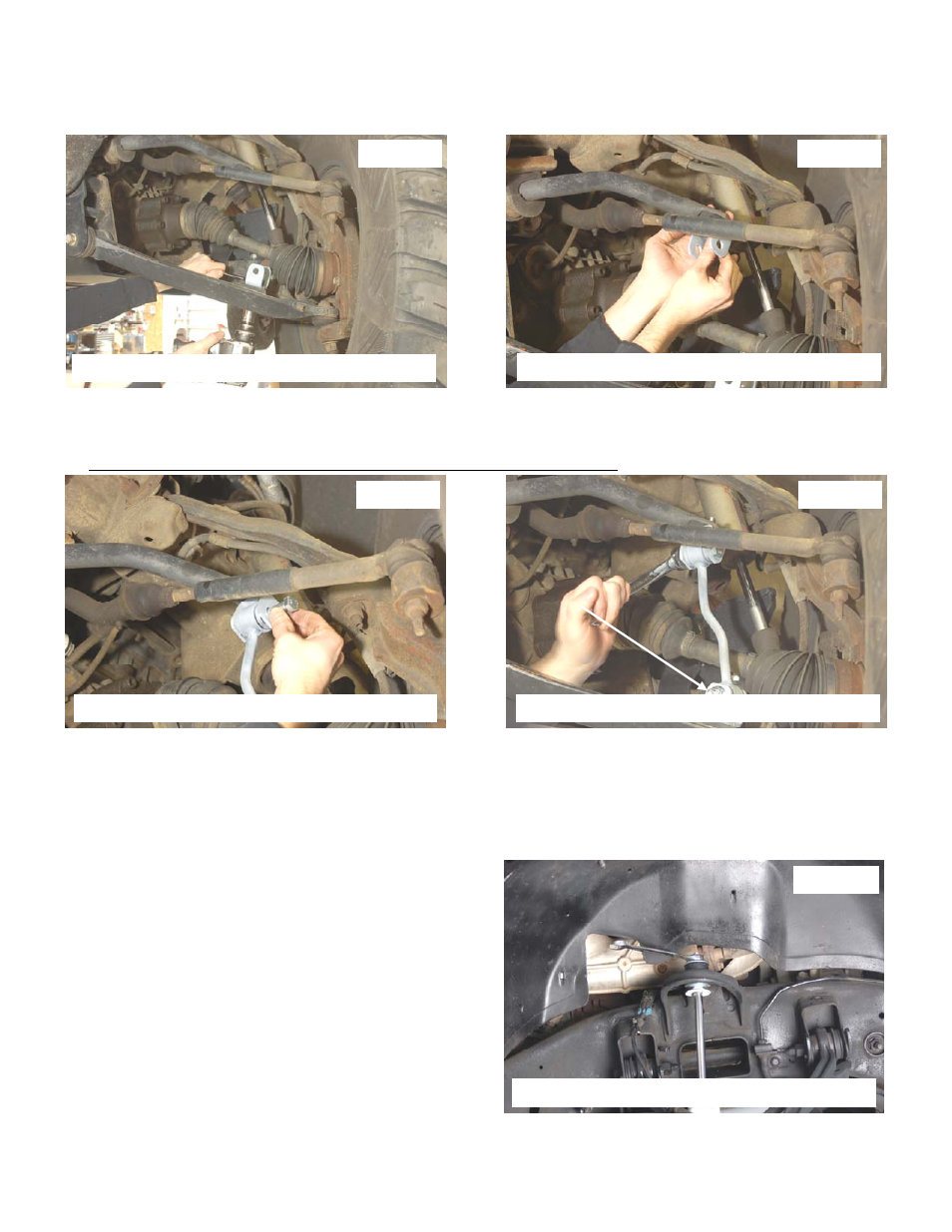
36. Install the supplied sway bar link bracket as shown in Photo 30 on the lower control arm using the supplied 12mm x
35mm bolt and flange lock nut. Tighten using a 18mm & 19mm wrench.
37. Install the upper sway bar link bracket as shown on the sway bar with the supplied 12mm x 35mm Bolt and flange
lock nut. See Photo 31.
38. Install the sway bar link in the upper bracket with the supplied 12mm x 65mm bolt and flange lock nut. See Photo
32. Tighten using a 18mm & 19mm wrench.
39. Install the sway bar link in the lower bracket and secure with the supplied 12mm x 65mm Bolt and flange lock nut.
The bolt will need to be installed as shown with the threads pointing forward. See Photo 33.
40. Slide the torsion bars back into the cross-member with the stock torsion bar adjusters. Match mark made earlier to
properly clock the torsion bar adjuster and the torsion bar.
41. Using a torsion bar tool, load the torsion bars using the mark made earlier as a reference.
42. Locate the supplied front shock absorbers and assemble with bushings/sleeves. Install front shock part #658441 in
the factory lower location as shown in Photo 34 with factory hardware and using a 21mm wrench. Install the shock
in the upper mount with supplied stem bushings, cup washers & nuts using a 9/16” wrench.
43. Install the tires and wheels and jack up the vehicle to
remove the jack stands. Lower the vehicle to the ground.
44. Tighten control arm hardware using a 18mm & 24mm
wrench.
Photo 34
Install shock absorbers
Photo 30
Photo 31
Photo 32
Photo 33
Install sway bar bracket on the lower arm
Install sway bar bracket on the sway bar
Install the link on the sway bar
Install the link on the arm and tighten