Milton CAT G200LG4 200kW_250kVA LG Installation Guide User Manual
Page 10
• In addition to the cooling effects of ambient air, the
vaporization process itself provides an additional
cooling effect.
1.7.5 GASEOUS FUEL SYSTEM PIPING
NOTE:
The information below is to assist in planning
gaseous fuel installation. In NO WAY should this
information be interpreted to conflict with appli-
cable fuel gas codes. Contact the local jurisdiction
if questions arise.
The following general rules apply to piping used in
gaseous fuel systems:
• The piping should be of black iron, rigidly mount-
ed and protected against vibration.
• Install the supplied length of flexible hose between
the generator connection point and rigid piping.
The supplied flexible hose is not to be installed
underground or in contact with ground. The
flexible hose is for in-line installation only.
Bends, kinks or off-center in-line installation of
flexible hose is NOT allowed.
• Piping must be of the correct size to maintain the
required supply pressures and volume flow under
varying conditions (see Table 2).
• Installed piping must be properly purged and leak-
tested, in accordance with applicable codes and
standards.
• Use an approved pipe sealant or joint compound
on all threaded fittings, to reduce the possibility of
leakage.
NOTE:
In the absence of local purging and leak test stan-
dards, NFPA No. 54 may be used as a guide.
1.8 ELECTRICAL
CONNECTIONS
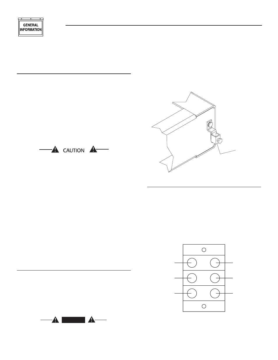
1.8.1 GROUNDING THE GENERATOR
A GROUNDING LUG is provided on the generator
mounting base for the purpose of grounding the
frame and the external electrically conductive parts
of this equipment to an approved earth ground and/
or grounding rods where required by the National
Electrical Code (Figure 1.4). Consult a qualified
electrician for grounding requirements in the area.
Groudning procedures must meet local regulations.
DANGER
Do not connect the ground wire to any pipe
that carries a flammable or explosive substance
– FIRE or an EXPLOSION may result.
Proper grounding helps protect personnel against
electrical shock in the event of a ground fault condi-
tion in the generator or in connected electrical devic-
es. In addition, grounding helps dissipate static elec-
tricity that often builds up in ungrounded devices.
Figure 1.4 – Generator Grounding Lug (typical)
GROUNDING
LUG
1.8.2 BATTERY CHARGER CONNECTION
The generator has been equipped with a 2 Amp bat-
tery charger installed in the control panel. Power
leads for the charger have been run to the connec-
tion box (Figure 1.5). On units equipped with 2.5L
engines, this connection is found in the control panel.
The terminals will need to be supplied from a
120VAC, 15 Amp circuit.
Figure 1.5 — Battery Charger Connection
Customer
to provide
120 VAC
15 Amp
Factory
provided
connection
to battery
charger in
control
panel.
{
}
(See the wiring diagram in the Owner's Manual that
is supplied with the unit.)
8
Section 1 - General Information
Liquid-cooled Generators