B attaching the ceiling mount cover, C mounting options, D attaching the brackets to the display – Atdec Telehook TH-3070-CTW Installation manual User Manual
Page 2: E attaching horizontal rail, F position sliders, Option 1, Option 2, Option 3, Option 4, Step 2
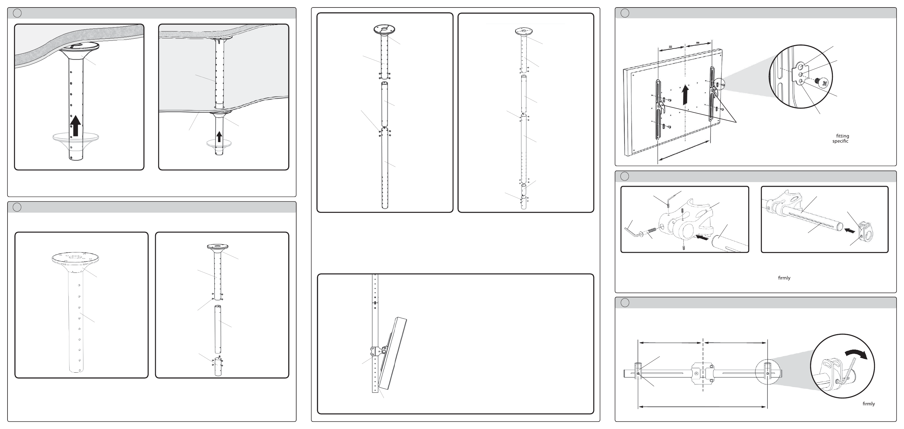
B Attaching the Ceiling Mount Cover
Slide cover plate up.
Ceiling Mount
Cover
If the ceiling mount is attached where a false ceiling is used,
the ceiling mount cover should be used to hide the hole in
the false ceiling.
Ceiling Mount
Cover
Ceiling Mount
False Ceiling
C Mounting Options
Option 1:
To mount the display from 220mm (8
11
/
16
”) to 470mm (18
1
/
2
”)
please use the above set up as shown. Settings are at 50mm
(2”) increments.
*See note.
Ceiling Mount
Cover
Option 2:
To mount the display from 650mm (25
1
/
2
”) to 1000mm
(39
3
/
8
”) please use the above set up as shown. The Inner
Hanger position can be adjusted at 50mm (2”) increments.
Ceiling Mount
Cover
Ceiling Mount
M8x10mm
Screws
There are four possible mounting options for the Telehook Flat Panel Ceiling Mount. The selected mounting option will be deter-
mined by the required distance from the ceiling to the centre of the display.
Ceiling Mount
Option 1: 220mm (8
11
/
16
”) - 470mm (18
1
/
2
”)
Option 2: 650mm (25
1
/
2
”) - 1000mm (39
3
/
8
”)
I
nner Hanger
Collar Joiner
Option 3:
To mount the display from1070mm (42
1
/
8
”) to 1820mm (71
5
/
8
”)
please use the above set up as shown. The Inner Hanger
position can be adjusted and the Collar can be mounted along
the holes on the Extension hanger. Settings are at 50mm (2”)
increments.
*See Note.
Ceiling Mount
Cover
Option 4:
To mount the display from 1650mm (65”) to 2000mm (78
3
/
8
”)
please use the above set up as shown. Note that the Inner
Hanger position can be adjusted, and that the Collar will be
mounted to the Collar Joiner. Settings are at 50mm (2”)
increments.
Ceiling
Mount Cover
Ceiling Mount
M8x10mm
Screws
Ceiling Mount
Option 3: 1070mm (42
1
/
8
”) - 1820mm (71
5
/
8
”)
Option 4: 1650mm (65”) - 2000mm (78
3
/
8
”)
Extension
Hanger
Collar Joiner
M8x10mm
Screws
Extension
Hanger
Inner Hanger
Point of Contact
*NOTE:
If you intend to mount the display along the hanger
as per Option 1 or Option 3, you may choose to cut
the excess hanger, for improved aesthetics and cable
management.
Cut
Inner Hanger
Hanger Joiner
D Attaching the Brackets to the Display
M8 Screw Hole
M6 Screw Hole
M5 & M4
Screw Hole
Step 2:
Use the supplied Multi Washer as shown
above. Ensure that the tightest
hole
in the washer is used for the
size
screw. Note distance X, for use in
the following steps.
=
=
TOP
Clinch Nuts
Multi Washer
Step 1
Attach left and right brackets to the rear of your display. Select M4, M5, M6 or M8 fasteners to suit your display. Ensure
a minimum of 2 fasteners are used per bracket. Clinch nuts must be positioned as shown (internally).
E Attaching Horizontal Rail
Collar Front
Step 1
Insert the Horizontal Bar into the Hanger Pole Collar. Ensure
the slots on the Horizontal Bar are facing towards the Collar.
Insert the M8x55mm Screw to hold the bar in position.
Loosely insert the three M6x12mm grub screws.
M8x55mm
Screw
M6x12mm
Grub Screw
Horizontal
Rail
Step 2
Attach the two sliders to the Horizontal Bar, one on either
side. Tighten the grub screw into the slot, however do not
tighten
as the position will need to be adjusted to suit
your display.
Slider
Grub Screw
Slot
Horizontal Bar
F Position Sliders
=
=
Slider
Grub
Screw
Step 2
Secure slider in position and tighten
with
supplied allen key. Ensure that the grub screw
tightens into the slot on the horizontal bar.
X
Tighten
Distance X
Step 1
Accurately position sliders at Distance X as recorded in Section D. Ensure the
Sliders are equally spaced along the centre Horizontal Bar.
5mm
Allen Key
3mm Allen Key