Mounting options, Attaching the display, Direct mount configuration – Atdec Spacedec SD-SA-DK Installation manual User Manual
Page 2: Installing cable management, Attaching the cable wrap to the arm, Tighten firmly tighten firmly
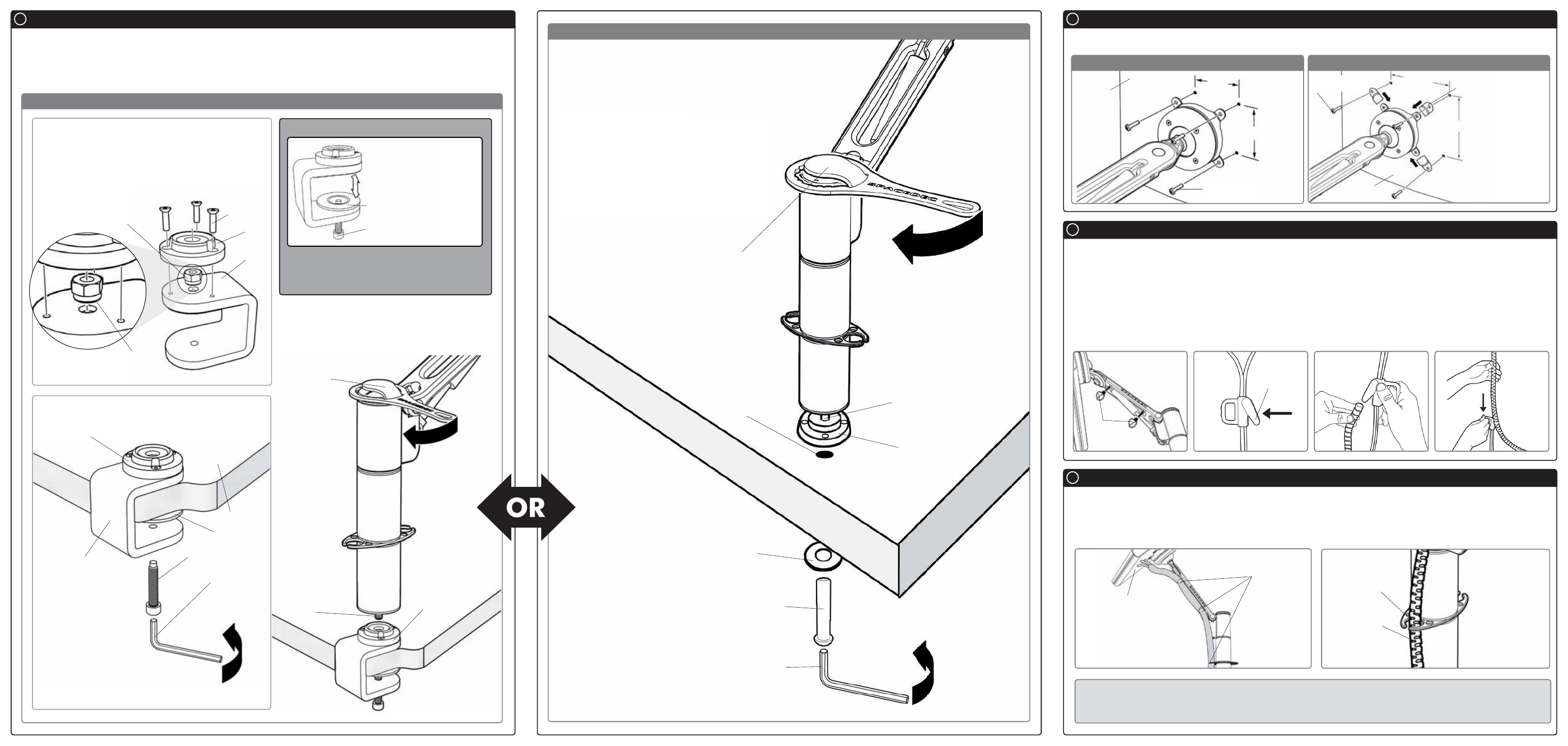
C.1. Desk Clamp
C.2. Bolt Through
Mounting Options
C
There are two Mounting Options: Desk Clamp and Bolt Through
To use the Desk Clamp (Suits desktop thicknesses of 12mm-38mm [
1
/
2
”
-1
1
/
2
”
]) follow the Desk Clamp
instructions at C.1. To use the Bolt Through system (Suits desktop thicknesses of 12mm-40mm [
1
/
2
”
-1
1
/
2
”
])
follow the Bolt Through instructions at C.2.
To assemble the Desk Clamp Assembly, first place
the M8 Nyloc Nut inside the Base Casting with
the Plastic Ring facing down, then screw the Base
Casting on to the Desk Clamp Bracket using the
M4x16mm Countersunk screws.
C.1.1. Assemble the Desk Clamp
C.1.2. Attaching the Desk Clamp
Tighten
Firmly
Washer
M8 Interscrew
5mm Allen Key
Threaded
Rod
Base
Casting
Top Cap
Tool
Base Casting
Desk Clamp
Assembly
Desk Top
Pressure Plate
M8 Desk Clamp Screw
5mm Allen Key
Attaching the Display
D
Direct Mount Configuration
75mm x 75mm (3” x 3”) mounting hole pattern
100mm x 100mm (4” x 4”) mounting hole pattern
Installing Cable Management
E
Attaching the Cable Wrap to the Arm
F
E.1.
Push the two supplied Cable Clips into the holes on the underside of the arm as shown in diagram
E.2.
Feed the cables into the Cable Wrap Applicator.
E.3.
Insert the Cable Wrap Applicator into the Cable Wrap as shown.
E.4.
Squeeze the nose of the Applicator and place inside the Cable Wrap ensuring that the opening edges
of the Cable Wrap face towards the nose of the applicator as shown in diagram.
F.1.
Position the display at its highest possible position to ensure that there is sufficient cabling at the end of
the arm so the cables are not stretched or pulled out when the display is moved.
F.2.
Clip the cable wrap into the Cable Tube Manager Clips as shown in diagram.
BEFORE PROCEEDING TO THE NEXT STEP PLEASE NOTE:
Swing Arm will only work when a display is properly installed.
DO NOT
adjust tension screws or gas strut until your display has been attached.
Cable Clips
Display at
highest point
Cable Tube
Manager Clip
Cable Wrap
E.1.
Push in
Clips
NOTE:
Ensure that
the flat side of
each Extension
Clip sits against
the back of the
display
Extension Clip
4x12mm or
4x16mm Screws
Display
4x10mm
Screws
C.2.1. Drill Mounting Hole
Drill a 13mm (1/2”) hole in your work surface
at the desired location for your arm.
C.2.2. Install as shown
Insert the M8 Interscrew up through the hole in
the work surface.
Using both hands, secure the M8 Interscrew
with the 5mm Allen Key supplied in the Desk
Clamp Box and use the other hand to tighten
the Threaded Rod into the Interscrew with the
supplied Top Cap Tool.
F.1.
75mm
(3”)
75mm (3”)
100mm
(4”)
100mm (4”)
Nose
E.2.
E.3.
E.4.
F.2.
Adjust the Desk Clamp to suit your desk
thickness by turning the M8 Desk Clamp
Screw with the supplied 5mm Allen Key
Suits 12mm
(
1
/
2
”) to 38mm
(1
1
/
2
”) thick
Work Surfaces
Pressure Plate
M8 Desk
Clamp Screw
Display
M4x16mm
Countersunk
Screw (x3)
Base
Casting
M8 Nyloc
Nut
Desk
Clamp
Bracket
C.1.3. Attaching the Swing Arm Post
Use the Top Cap Tool to tighten the Threaded Rod
into the Base Casting as shown below:
Top Cap
Tool
Threaded
Rod
Base
Casting
NOTE: Desk Clamp
Assembly is suitable for
square edged desks only.
Plastic
Ring
Tighten
Firmly
Tighten
Firmly
NOTE: It is
recommended
that the Desk
Clamp be
attached to the
rear or side
edge of the
work surface
DESK CLAMP ADJUSTMENT RANGE
13mm (
1
/
2
”) hole