Th-1040-ct installation instructions_new_webp2, Installation complete, Step 9. cable management – Atdec Telehook TH-1040-CTS Installation manual User Manual
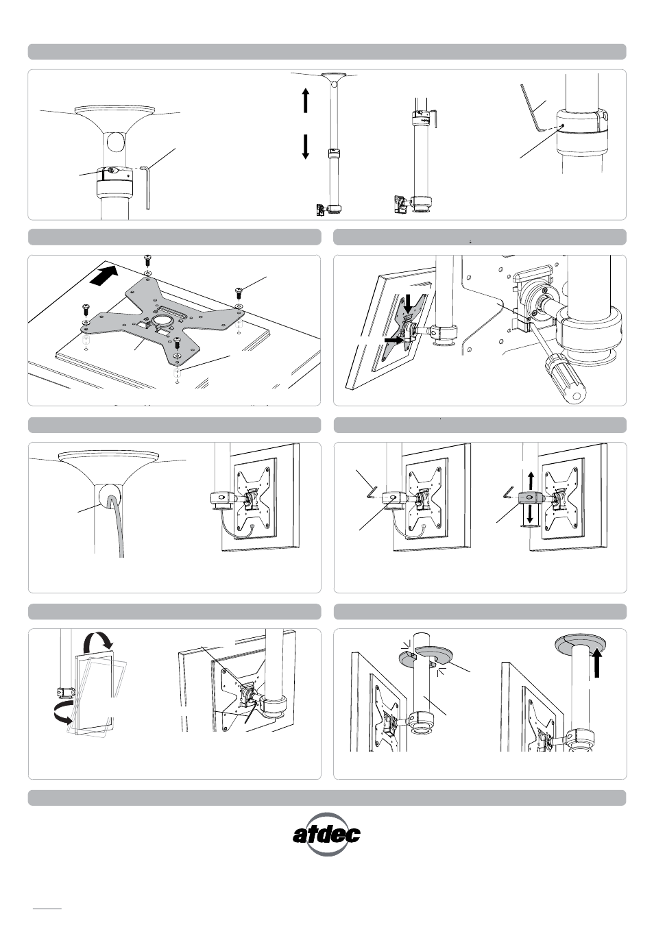
Page 2: Step 8. attach display to pole assembly, Step 10. height adjustment, Step 7. attach vesa plate to display, Step 11. final adjustment, Step 12. install false ceiling cover, Step 6. set height of pole
Set Screw
Cable
Access Port
Installation Complete
No portion of this document or any artwork contained herein should be reproduced in any way without the express written consent Atdec Pty Ltd.
Due to continuing product development, the manufacturer reserves the right to alter specifications without noticed. Published 29.09.11 ©
Step 6. Set Height of Pole
Step 9. Cable Management
A. Whilst supporting the lower half of Pole
Assembly loosen the Socket Cap Screws (x2).
B. Slide Pole Assembly
to the desired height.
C. Tighten the Socket Cap
Screws (x2) to set the height.
Step 8. Attach Display to Pole Assembly
A. Feed cables down the Pole
Assembly through the Cable
Access Port.
B. Pull cables out from lower
half of the Pole Assembly and
connect to Display.
Step 10. Height Adjustment
Pole Joint
LOOSEN
TIGHTEN
FIRMLY
Socket Cap
Screw
5mm Allen Key
ADJUST
HEIGHT
A. Loosen Socket Cap
Screws (x2) on the Donut.
TILT
PAN
Step 7. Attach VESA Plate to Display
TOP
Step 11. Final Adjustment
A. Pan, Tilt and Rotate
the Display as required.
D. If necessary, centralise the
Pole Joint by tightening the
Set Screws (x2) to suit.
2.5mm
Allen Key
VESA plate
Mounting
Screws
B. Slide the height of the
Donut as required. Tighten
Socket Cap Screws to lock.
Step 12. Install False Ceiling Cover
PORTRAIT TO
LANDSCAPE
Choose the appropriate mounting hardware to suit the Display.
Spacers
(optional, for recessed
mounting holes)
B. PUSH
HOOK
A.
(optional) Once Display
is attached, insert
Security Screw using
Phillips-head screwdriver
C.
Security
Screw
Socket Cap
Screw
5mm
Allen Key
VESA Ball Mount
Tension Plate at rear
3mm Allen Key
B. If necessary tighten the VESA
Ball Mount by adjusting the
Tension Plate. Using the 3mm
Allen Key adjust screws evenly.
Donut
SLIDE
False Ceiling
Cover
CLICK
Lower Pole
If the Lower Pole hangs below a suspended ceiling, clip the False
Ceiling Cover over the Lower Pole, and push up to the ceiling.
PUSH