Un-lock: lock, D mount the display, E cable management – Atdec Visidec VF-M Installation manual User Manual
Page 2
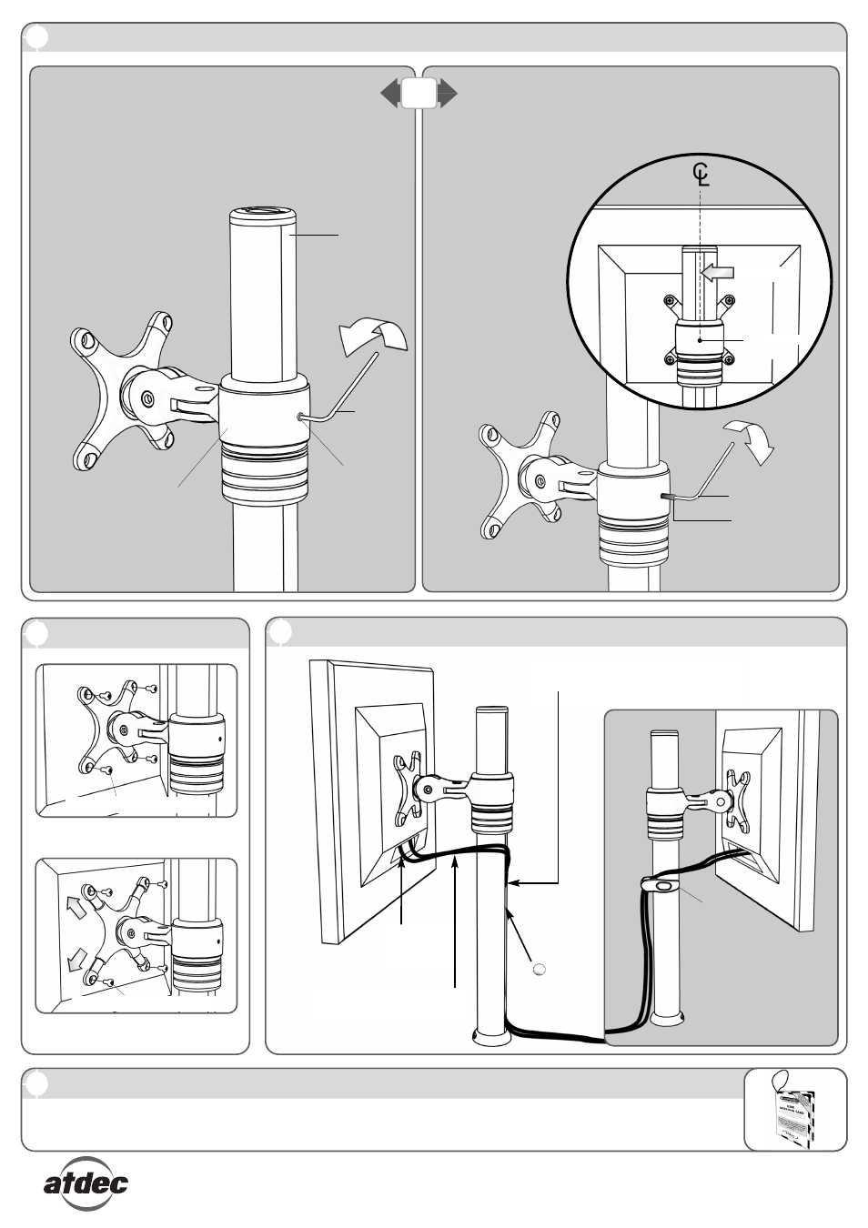
D Mount the Display
No portion of this document or any artwork contained herein should be reproduced in any way without the express written consent of Atdec Pty Ltd.
Due to continuing product development, the manufacturer reserves the right to alter specifications without notice. Published: 16.01.08 ©
For Displays with 75mm x 75mm
(3” x 3”) mounting hole patterns
M4 Display Mounting Screws
Step 1:
Connect
cables
NOTE: Leave enough slack in the
cables to allow for movement
E Cable Management
NOTE: If Focus Micro
is to be used in a multi-
user environment, use
the supplied Cable Clip
to secure the display’s
cables to the pole.
C Unlock/Lock Arm Rotation (Note: Focus Micro comes assembled in the “Locked” position.)
If you wish your Focus Micro Arm to have 360° rotation
about the Pole you will need to un-lock the arm’s rotation.
2mm
Allen Key
For Displays with 100mm x 100mm
(4” x 4”) mounting hole patterns
M4 Display Mounting Screws
F Leave the “User Operating Card” with Visidec Focus Micro
Leave the “User Operating Card” secured to the Visidec Focus Micro for the user’s reference.
Step 2: Insert cables into slot, using cable
balls to hold them in place
(single user only)
Cable
Balls (x2)
Step 1:
Ensure the hole for the
Grub Screw in the Micro
Arm is lined up with
the centre of the Slot
in the pole.
Step 2:
Re-insert the Grub
Screw previously
removed. Turn the
Grub Screw clockwise
until it is tight. Do
not over-tighten
UN-LOCK:
LOCK:
2mm Allen Key
Slot In Pole
Pole
Micro Arm
Cable
Clip
Grub Screw
OR
Step 1:
Unlock the arm by turning
the Grub Screw anti-
clockwise removing the grub
screw completely.
(NOTE: Store the Grub
Screw in a safe place if you
are to return the arm to the
Locked position.)
If you have un-locked the Focus Micro Arm, but wish to fix
rotation around the pole, you will need to lock the arm.
Grub Screw
Hole
Grub Screw