Altronix Maximal77 Installation Instructions User Manual
Page 17
Maximal11/Maximal33/Maximal55/Maximal77/Maximal75 Access Power Controllers (Fused)
- 17 -
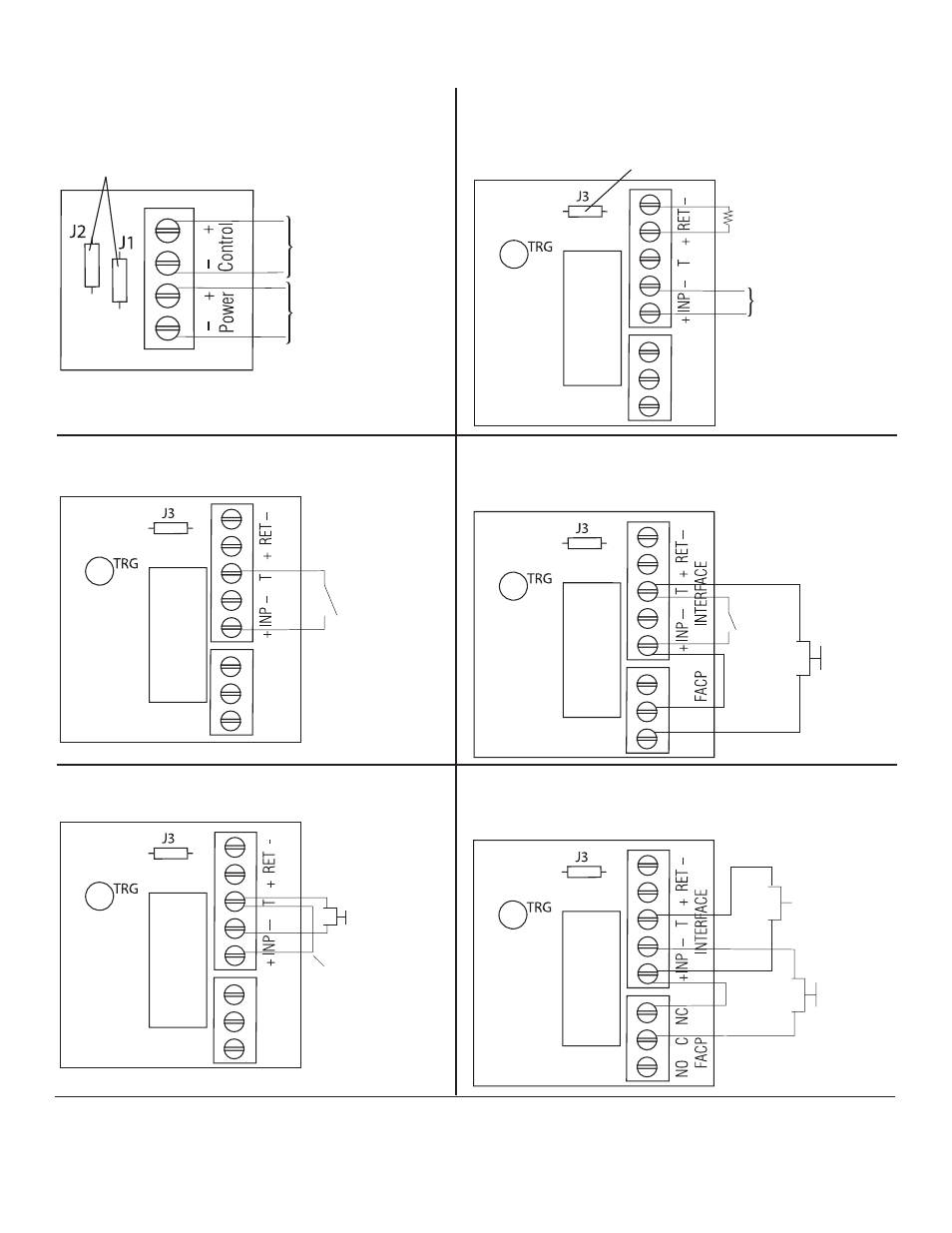
ISOLATED POWER INPUT
12 OR 24 VAC OR VDC
(LOCK POWER)
ISOLATED POWER INPUT
12 OR 24 VAC OR VDC
(ACM8 POWER)
CUT JUMPERS
J1 AND J2
CUT
JUMPER J3
FROM FACP
SIGNAL OUTPUT
CIRCUIT
+
--
FACP
SIGNAL CIRCUIT
OUTPUT EOL
NO C NC
FACP INTERF
ACE
JUMPER
N.C. DRY
TRIGGER
INPUT
NO C NC
FACP INTERF
ACE
N.C. TRIGGER
INPUT
N.C. RESET
SWITCH
JUMPER
N.O. TRIGGER
INPUT
NO C NC
FACP INTERF
ACE
N.C.
RESET
SWITCH
N.O.
TRIGGER
INPUT
JUMPER
NO C NC
FACP/Optional Power Supply Hook-up Diagrams:
Fig. 12 Normally Open - Non-Latching FACP
trigger input:
Fig. 13 Normally Open FACP Latching trigger input
with reset:
(This output has not been evaluated by UL)
Fig. 14 Normally Closed - Non-Latching FACP
trigger input:
Fig. 15 Normally Closed - Latching FACP trigger input
with reset:
(This output has not been evaluated by UL)
Fig. 11 Polarity reversal input from FACP signaling circuit
output (polarity is referenced in alarm condition):
Fig. 10 Optional hook-up using two (2) isolated power
supply inputs (Only applicable on Maximal11):