Fig. 4 maximal77, Fig. 4a, Optional 12vdc battery** optional 12vdc battery – Altronix Maximal77 Installation Instructions User Manual
Page 11: Power supply board
Maximal11/Maximal33/Maximal55/Maximal77/Maximal75 Access Power Controllers (Fused)
- 11 -
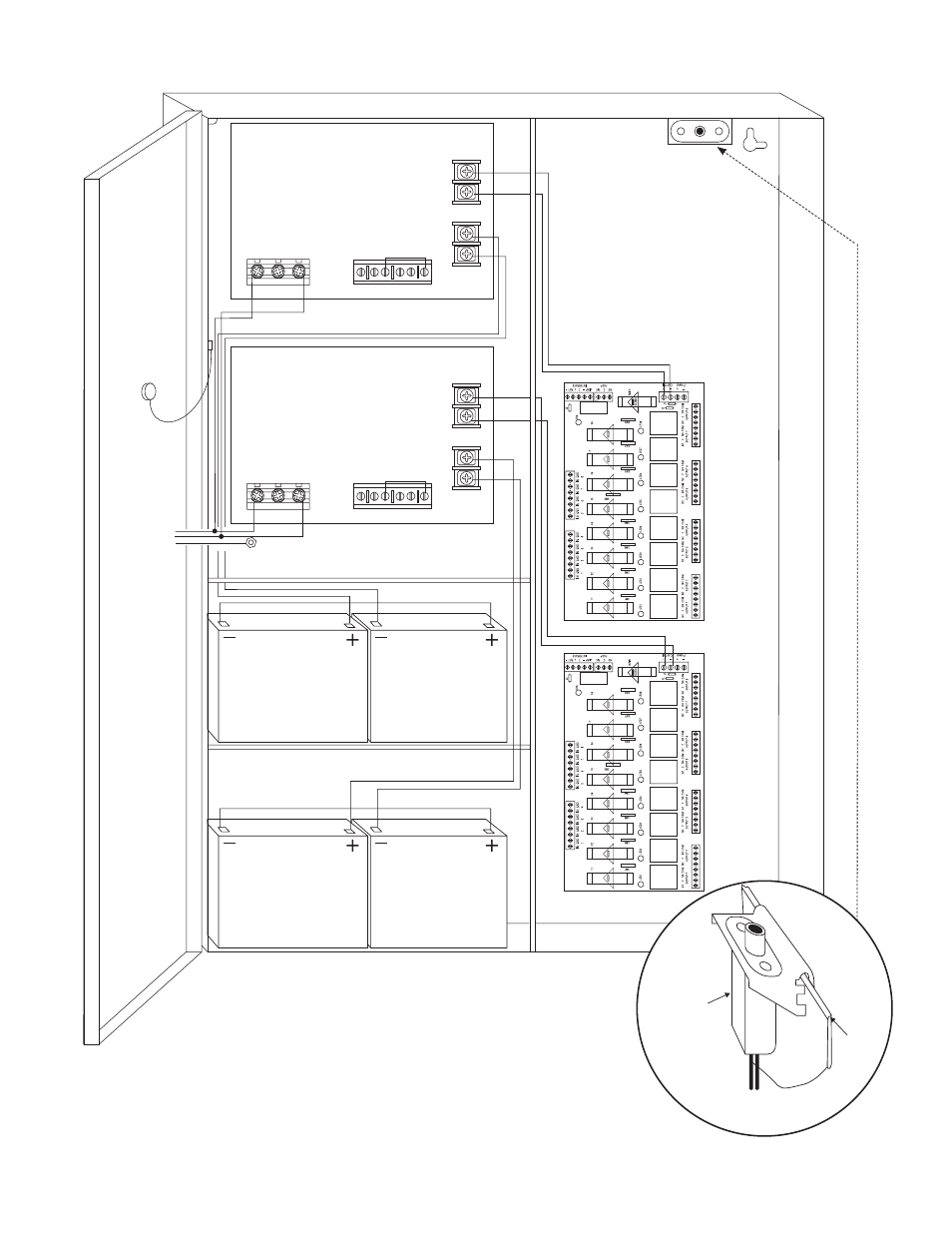
Fig. 4
Maximal77
2.5A 250
V
2.5A 250V
2.5A 250V
2.5A 250V
2.5A 250V
2.5A 250
V
2.5A 250V
2.5A 250V
2.5A 250V
2.5A 250V
2.5A 250V
2.5A 250V
2.5A 250V
2.5A 250
V
2.5A 250V
2.5A 250V
+
DC
---
BAT FAIL
NC C NO NC C NO
– BA
T
+
AC FAIL
Power Supply Board
L G N
+
DC
---
BAT FAIL
NC C NO NC C NO
– BA
T
+
AC FAIL
Power Supply Board
L G N
115VAC Input
60 Hz.
Optional
12VDC Battery**
Optional
12VDC Battery**
Wire
Strap
(from
Enclosure
to Door)
Tamper Switch
Optional
12VDC Battery**
Optional
12VDC Battery**
Ground Lug
Line
Neutral
Ground
Line
Neutral
**24VDC operation: Connect two (2) 12VDC
batteries in series
Fig. 4a
Edge of
Enclosure
to Access Control Panel
or U.L. Listed
Reporting Device
Enclosure
Sentrol
model # 3012
Tamper Switch
or equivalent
(Not Included)
- NetWay3012 Installation Instructions (2 pages)
- HubWay 16Di Data Sheet (2 pages)
- HubWay Dvi Data Sheet (1 page)
- HubWay Av2 Data Sheet (1 page)
- PD4CB Installation Instructions (1 page)
- ACM4CB Data Sheet (2 pages)
- VertiLine63D Data Sheet (2 pages)
- eBridge16CR Installation Instructions (8 pages)
- LPS3WP12 Data Sheet (2 pages)
- VertiLine246D Data Sheet (2 pages)
- T24130D Data Sheet (1 page)
- eBridge1PCRTX Data Sheet (2 pages)
- RB5 Installation Instructions (1 page)
- Tempo2 Data Sheet (1 page)
- BC600G Data Sheet (1 page)
- eBridge1CRT Data Sheet (2 pages)
- AL400ULB Data Sheet (1 page)
- PT2724 Installation Instructions (8 pages)
- OLS180 Installation Instructions (2 pages)
- HubWay 8CD Data Sheet (2 pages)
- AL175ULB Data Sheet (1 page)
- StrikeIt2 Installation Instructions (8 pages)
- LPD Data Sheet (1 page)
- eBridge4SK Installation Instructions (8 pages)
- LPS3AC Installation Instructions (2 pages)
- T2428100 Data Sheet (1 page)
- TP1650 Data Sheet (1 page)
- T2885D Data Sheet (1 page)
- T2428175 Installation Instructions (1 page)
- T1656 Installation Instructions (1 page)
- SMP3 Data Sheet (1 page)
- RBR1224 Data Sheet (1 page)
- HubWay LD16D Data Sheet (2 pages)
- eFlow102NX16D Installation Instructions (16 pages)
- T24175C Data Sheet (1 page)
- Maximal5D Data Sheet (2 pages)
- Maximal7 Installation Instructions (16 pages)
- HubWay 8CDS Data Sheet (2 pages)
- eFlow4NX8D Installation Instructions (16 pages)
- MOM5C Data Sheet (1 page)
- eBridge16PCRX Installation Instructions (8 pages)
- HubWay EX16SP Data Sheet (2 pages)
- T24130C Installation Instructions (1 page)
- Maximal5 Data Sheet (2 pages)