Fig. 5 maximal75, Fig. 5a, Optional 12vdc battery** optional 12vdc battery – Altronix Maximal77 Installation Instructions User Manual
Page 12: Power supply board
- 12 -
Maximal11/Maximal33/Maximal55/Maximal77/Maximal75 Access Power Controllers (Fused)
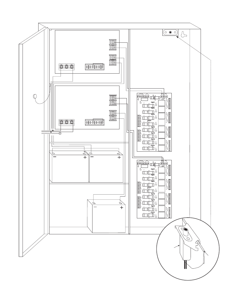
Fig. 5
Maximal75
2.5A 250V
2.5A 250V
2.5A 250V
2.5A 250
V
2.5A 250V
2.5A 250V
2.5A 250V
2.5A 250V
2.5A 250V
2.5A 250V
2.5A 250V
2.5A 250V
2.5A 250V
2.5A 250V
2.5A 250V
2.5A 250V
+
DC
---
BAT FAIL
NC C NO NC C NO
– BA
T
+
AC FAIL
Power Supply Board
L G N
–
DC
+
BAT FAIL
NC C NO NC C NO
+ BA
T
---
AC FAIL
Power Supply Board
L G N
115VAC Input
60 Hz.
Optional
12VDC Battery**
Optional
12VDC Battery**
Wire
Strap
(from
Enclosure
to Door)
Tamper Switch
Ground Lug
Line
Ground
Neutral
Line
Neutral
Optional
12VDC Battery*
*12VDC operation: For 12VDC operation
only a single battery is needed.
Connect red battery lead
to terminal marked
[+ BAT] and to the
[positive (+)] terminal
of the battery. Connect
black battery lead to
terminal marked [BAT -]
and to the [negative (-)]
terminal of the battery.
**24VDC operation: Connect two (2) 12VDC
batteries in series
Fig. 5a
Edge of
Enclosure
to Access Control Panel
or U.L. Listed
Reporting Device
Enclosure
Sentrol
model # 3012
Tamper Switch
or equivalent
(Not Included)