2 connection procedure – VEGA VEGASON 65 Foundation Fieldbus User Manual
Page 25
T
ake note of the corresponding installation regulations for Ex
applications. In particular, make sure that no potential equalisation
currents flow over the cable screen. In case of grounding on both sides
this can be achieved by the use of a capacitor or a separate potential
equalisation.
5.2 Connection procedure
Warning:
B
efore connecting to voltage supply, the plug connection between
transducer and remote electronics must be provided in idle condition
(
see illustration below). Non-observance will damage the electronics!
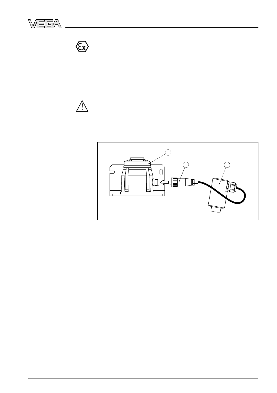
1
2
3
Fig. 18: Plug connector between transducer and socket of electronics housing
1
Socket electronics housing
2
Plug connector
3
Connection piece, transducer tube
O
nly then, the sensor may be connected to voltage supply.
P
roceed as follows:
1
U
nscrew the housing cover
2
L
oosen compression nut of the cable entry
3
R
emove approx. 10 cm (4 in) of the cable mantle (current output),
strip approx. 1 cm (0.4 in) insulation from the ends of the individual
wires
4
I
nsert the cable through the cable gland into the sensor
5
L
ift the opening levers of the terminals with a screwdriver
6
I
nsert the wire ends into the open terminals according to the wiring
plan
7
P
ress down the opening levers of the terminals, you will hear the
terminal spring closing
Select connec-
tion cable for Ex
applications
VEGASON
65 • F
oundation Fieldbus
25
5 C
onnecting to power supply
28794
-
EN
-081127