VEGA VEGASON 65 Foundation Fieldbus User Manual
Page 16
V
ersion C is supplied in three parts:
l
T
ransducer
l
T
ransducer cable
l
electronics for wall mounting
A
ssemble the version as follows:
1
L
oosen the screws on the fixing ring (4) with a hexagon spanner
(
size 4), remove the transducer tube out of the swivelling holder
2
M
ount the flange
3
I
nsert the transducer tube in the requested length from below into
the swivelling holder
4
F
asten with screws (4); torque max. 10 Nm
5
R
emove the plug from below out of the connection head and plug
it into the socket of the transducer tube
6
P
lug the connection head to the transducer tube. Do not squeeze
any cables. The cylinder is in the correct position, if the lower
notch (2) of the transducer tube is no longer visible
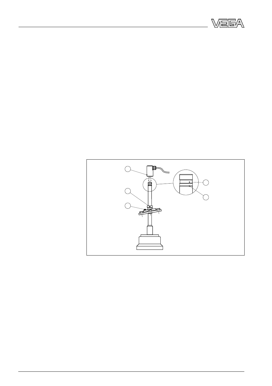
1
2
3
4
5
Fig. 6: Mounting - Version C
1
Groove for locking the connection head
2
Notch
3
Screw of swivelling holder (hexagon SW 13)
4
Grub screw, fixing ring (hexagon spanner - size 4)
5
Terminal screws, connection head (hexagon spanner - size 4)
7
T
ighten the screws (5) on the cylinder moderately with an Allen
wrench (size 4)
8
L
oosen terminal screw of the swivelling holder (3) with a fork
spanner (SW 13)
9
D
irect the sensor with the swivelling holder to the measured
product
10 F
asten the swivelling holder with screw (3), torque max. 20 Nm
Mounting - Version C
16
VEGASON
65 • F
oundation Fieldbus
4 M
ounting
28794
-EN
-081127