Hook switches (additional board) – VEGA VEGACOM 557 VEGA ASCII protocol User Manual
Page 22
22
VEGACOM 557 VEGA ASCII
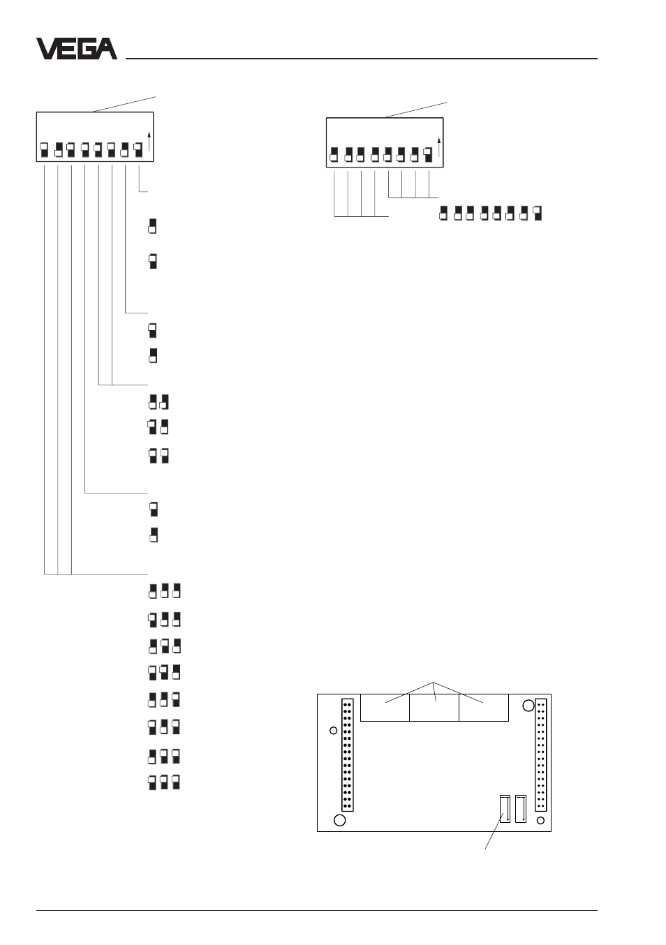
View of the dismounted additional print
Possible settings of DIL switch block 2 on additional
board
Possible settings of DIL switch block 3 on additional
board
Switch settings on VEGACOM 557
Note:
With the switch for the adjustment of the bus
address (DIL-switch block 3), it is theoreti-
cally possible to set addresses in the range
of 0 to 15. However, in reality only address 1
to 9 can be directly set. Address settings
outside the range are converted to address
9.
Address 0 cannot be used, as it is used as
broadcast address.
Hook switches (additional board)
The hook switches on the additional board
enable selection between TTY and RS 232
interface. The additional print has to be re-
moved from the basic print to modify the
settings. The following illustration shows the
removed additional print.
L R
L R
1
2
1
2
3
Hook switch
DIL switch
DIL switch block 2
(additional board)
Selection of the baud rate
Number of data bits
1200
600
300
8
7
Factory setting
9600
2400
19200
4800
38400
Parity
none
odd
even
Protocol mode
Modbus ASCII
Modbus RTU
DCS measured value image
(only relevant on VEGAMETs)
all meas. values Met 1,
all meas. values Met 2,
etc.
1. meas. value Met 1,
1. meas. value Met 2,
etc.
1
2
3
4
5
6
7
8
ON
1
2
3
4
5
6
7
8
ON
DIL switch block 3
(additional board)
Bus address
of VEGACOM 557
(Adr. 1 to 9)
Factory setting
e.g.:
Adr.
= 1
not used