Connections of the multiple plug (rear), Mounting and electrical connection, D b z – VEGA VEGACOM 557 VEGA ASCII protocol User Manual
Page 16
16
VEGACOM 557 VEGA ASCII
VEGA ASCII via RS 422
Wiring regulation for VEGA ASCII via RS 422
RS 422
RS 422
RS 422
RS 422
Wiring regulation for VEGA ASCII via RS 232 C
RS 232 C
RS 232 C
RS 232 C
RS 232 C
VEGA ASCII via RS 485
Wiring regulation for VEGA ASCII via RS 485
RS 485
RS 485
RS 485
RS 485
Mounting and electrical connection
VEGA ASCII via RS 232 C
Connection via modem
For remote parameter adjustment, it is possi-
ble to connect the PC interface via a modem.
In such a case, the modem cable that comes
with the respective modem should be used.
Modem operation is supported by VEGA-
COM 557 from software version 2.11. Further
information on the remote parameter adjust-
ment is stated in the operating instructions
"Remote parameter adjustment“.
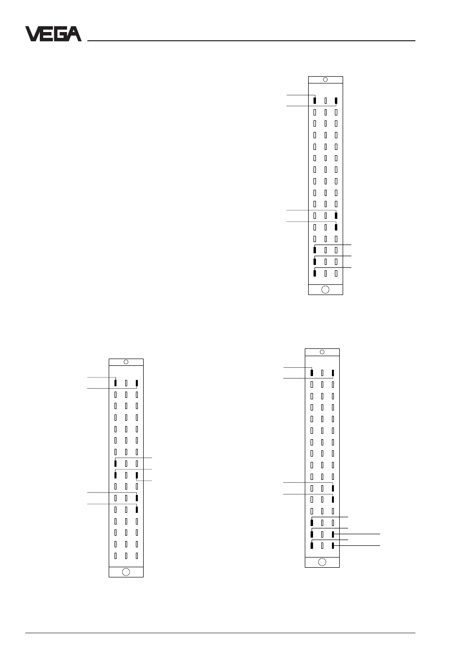
Connections of the multiple plug (rear)
For connection of VEGACOM 557 to the ex-
isting VEGA ASCII system all standard inter-
faces are available. The power supply of the
instrument and the connection to the VEGA
system are always the same. The following
illustrations show the respective terminal
assignments depending on the selected
interface type.
d b z
10
8
6
4
2
12
14
16
18
20
22
24
26
28
30
32
Supply voltage
GND
DISBUS (not
used on VEGA-
LOG)
–
TxD
RxD
+
–
+
Supply voltage
GND (C/C´)
DISBUS (not
used on VEGA-
LOG)
–
DATA (B/B´)
/DATA (A/A´)
+
–
+
Supply voltage
GND
DISBUS (not
used on VEGA-
LOG)
–
RX
/RX
+
–
+
d b z
10
8
6
4
2
12
14
16
18
20
22
24
26
28
30
32
d b z
10
8
6
4
2
12
14
16
18
20
22
24
26
28
30
32
TX
/TX