Hubcap assembly, Braided hose nut hubcap spindle – Spicer TIMS (Tire Inflation and Monitor System) for Trailers Installation Guide User Manual
Page 19
16
Installation
Installation
Hubcap Assembly
1.
Place hubcap gasket over rotary joint’s exit tube and
bulkhead adapter.
2.
Lubricate o-ring on the rotary joint’s bulkhead
adapter.
3.
From the inside, insert the bulkhead adapter through
the hole in the hubcap marked “Air.” Be sure to align
the flat on the bulkhead adapter to the flat inside the
hubcap. Attach the jam nut and hand tighten. When
properly seated, the top of the bulkhead adapter will
be flush with the top of the jam nut.
CAUTION: If wheels are installed, refer to Tire Hose In-
stallation on page 24 and Configuration, Clocking, and
Tire Hose Selection Chart on page 25 to determine cor-
rect “clocking” of hubcap. Wheel must be properly “clocked”
to hubcap to prevent hoses rubbing on the wheel. Failure to
properly “clock” hubcap may result in hose failure.
4.
Align the hubcap and gasket and install the 6 bolts.
Torque to the values listed in the Torque Values Chart
per manufacturers recommendations.
5.
Torque the rotary joint's jam nut to 10-12 lbs. ft.
6.
Install lubricant in wheel end to the correct level.
Torque Values Chart
CAUTION: Use of Pro-Torque spindle nuts may require
a hubcap spacer to prevent interference.
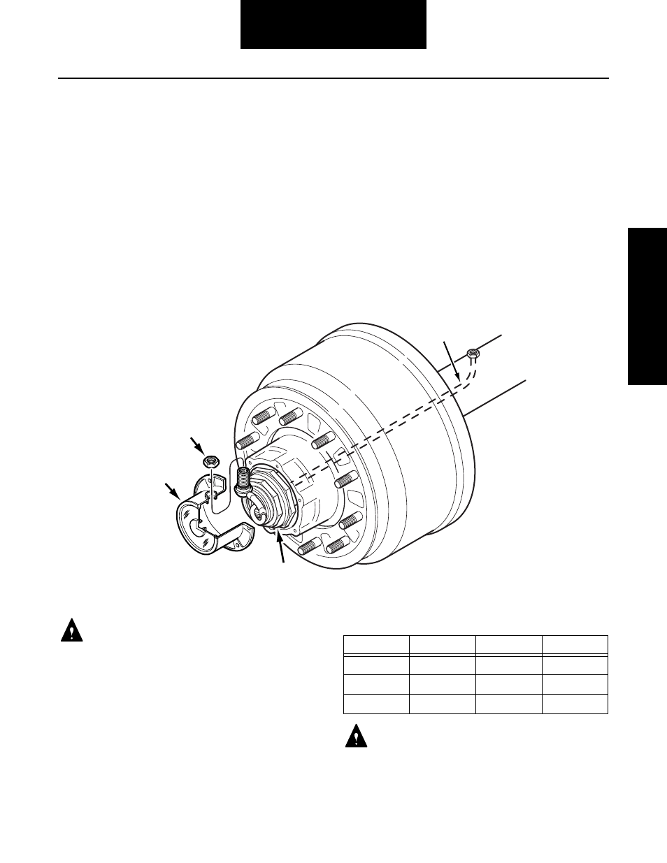
218UX014
Braided
Hose
Nut
Hubcap
Spindle
Hub Material
Bolt Grade
Bolt Size
Torque
Iron
5
5/16-18
16-19 lbs. ft.
Iron
8
5/16-18
22-27 lbs. ft.
Aluminum
5 & 8
5/16-18
10-12 lbs. ft.