Driveshaft, Spicer life, Series – heavy-duty – Spicer Axle, Driveshaft, Tire Management Systems, and Wheel-End Systems Specifications Guide 2013 User Manual
Page 25
This guide is periodically updated throughout the year. The most current information can be found on www.dana.com/cv
23
A
E
C
B
B
A
C
E
F
G
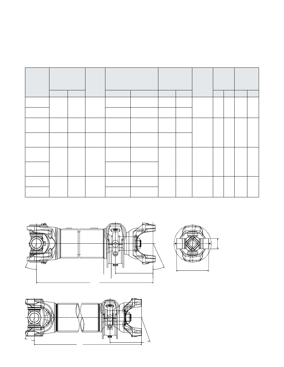
Fixed Yoke Coupling Shaft Assembly with Center Bearing
Driveshaft
Spicer Life
®
Series – Heavy-Duty
For additional configurations, contact Spicer Driveshaft Engineering for specific application information.
Coupling
Shaft
Assembly
Part
Number
Minimum Length
Centerline of Cross
to Centerline of
End Yoke
"A"
Maximum
Angle
"B"
Tube Size
Centerline of
Bearing to
Centerline of
End Yoke
"E"
Maximum
Angle
"C"
U-Joint
Span
"F"
Bearing
Cup
Diameter
"G"
MM
IN
MM
IN
MM
IN
MM
IN
MM
IN
SPL-140
140CS54025
350
13.79
25°
107.0 x 3.5 DOM 4.33 x .197 DOM
152
5.98
25°
139
5.46
49
1.93
SPL-140HD
140CS54013
110.0 x 5.0 DOM 4.33 x .197 DOM
154
6.08
SPL-170
170CS54019C
170CS54019F
368
14.47
25°
126.0 x 3.0 DOM 4.96 x .118 DOM
160
6.30
25°
164
6.46
55
2.17
SPL-170HD
170CS54017C
170CS54017F
368
14.45
25°
128.5 x 4.25 DOM 5.06 x .167 DOM
160
6.30
SPL-250
250CS54007C
250CS54007F
382
15.05
25°
128.5 x 4.25 DOM 5.06 x .167 DOM
164
6.46
25°
163
6.42
60
2.37
SPL-250HD
250CS54014C
250CS54014F
130.0 x 5.0 DOM 5.12 x .197 DOM
350CS54001
350CS54001F
386.2
15.20
15°
138.5 x 4.25 DOM 5.45 x .167 DOM
156.2
6.15
15°
172
6.77
65
2.56
350CS54002
350CS54002F
140 x 5.0 DOM
5.51 x .197 DOM