Overhaul and assemble output shaft assembly – Spicer Tandem Drive Axles Service Manual D170, D190, and D590 Series User Manual
Page 65
61
Output Shaft Assembly & Rear
Cover
Overhaul and Assemble Output Shaft Assembly
Note: Lubricate the parts with gear lube during assembly.
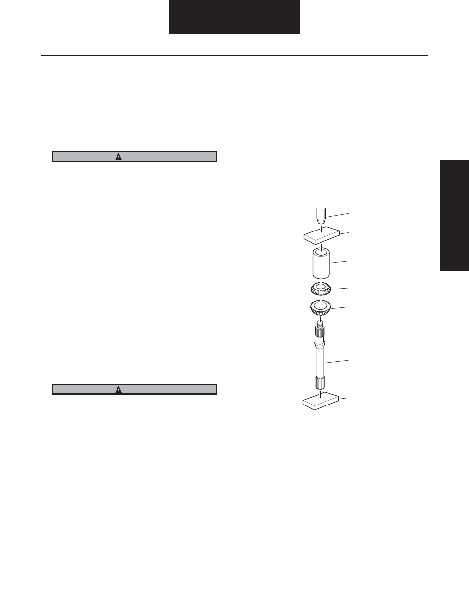
1. The output shaft bearings are assembled with both
bearing cones back to back. Use a press and a sleeve
to install one bearing at a time.
To prevent bearing damage, use a suitable sleeve that only
contacts the bearing race.
2. Apply pressure until the inner bearing cone touches
the shoulder of the output shaft.
3. Apply pressure until the back of the outer bearing
cone touches the back of the inner bearing.
Note: Axle housings with welded-on covers procured through
service will include the inner bearing cup as part of the
“service” axle housing assembly. Go to Step 6 if the inner
cup has already been installed.
4. Lightly coat the output bore of the axle housing
cover with a 9.5 mm (.38") wide application of Loc-
tite 680 where the bore contacts the inner bearing
cup. Do not apply Loctite outside of this area—to the
bearing rollers or outboard of the inner cup bore.
Improper application of the Loctite could lock the
rollers or cause excessive pre-load.
Add Loctite adhesive to the inner bearing surface of the
housing and NOT to the bearing race itself. If added to the
race, excessive adhesive could get on the surface of the
outer bearing race journal during installation and cure the
outer cap in place with excessive pre-load.
5. Using a sleeve and driver (hammer), install the inner
bearing cup.
6. Put the output shaft and bearing assembly into the
axle housing assembly.
7. Using a sleeve and driver (hammer), install the outer
bearing cup into the housing assembly over the out-
put shaft bearing cone.
8. Using snap ring pliers, install the snap ring that fas-
tens the outer bearing cup into the welded-on cover
assembly.
9. Check the endplay of the output shaft. New assem-
blies should measure 0.001" to 0.045" (0.03 to 1.143
mm).
Note: Use the bearing cup driver to insure seating of snap
ring after installation with snap ring pliers.
CAUTION
CAUTION
3
2
1
4
5
6
7
1 - Press
2 - Plate
3 - Sleeve
4 - Press Bearing on Second
5 - Press Bearing on First
6 - Output Shaft
7 - Plate
Ou
tp
ut Sh
aft A
ss
em
bly &
Re
ar C
ov
er