Wheel differential lock (optional equipment) – Spicer Drive Axles Service Manual Wheel Reduction Drive Axles (EA-50) User Manual
Page 15
Wheel Differential Lock (Optional Equipment)
Removal
Axle models indentified with a “D” suffix are
equipped with a manual locking differential.
Special methods are required to remove the
differential carrier from the axle housing.
IMPORTANT:
When removing axle shafts,
identify left and right shaft location for reference
during reassembly.
1. Drain axle lubricant and disconnect
driveline, following instructions for your
specificaxle.
2. Disconnect lead wires at optional selector
switch (if installed) and hydraulic line at
shift cylinder.
3. To facilitate removal of the differential
carrier assembly, the Differential Lock
should be engaged and held in the
engaged position. This can be
accomplished by one of two methods:
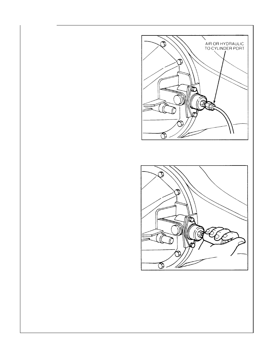
Air Pressure Engagement
Using an auxiliary air line, apply 80-120 psi air
pressure to shift cylinder air port to engage
clutch.
Manual Engagement
Install an 3/4-16 UNF bolt over 1.5" (38mm)
long, in the cylinder hydraulic port to manually
engage the clutches.
NOTE:
Hand-tighten the bolt... over-torquing
may cause damage to the shift unit. To
facilitate hand-tightening, coat bolt threads with
axle lube.
NOTE:
With either method, the axle shaft may
have to be rotated to permit the clutch to
become engaged.
4. Continue removing differential carrier as
sembly following instructions for your
specific axle.
13